Mitsubishi FX Series Basic Program Output Instructions: PLC Programming with Reset, OUT, PLF, PLS
Published on Oct05, 2024 | Category: OutputShare this Page:
A program is a connected series of instructions written in a language that the PLC can understand. There are three forms of program format; instruction, ladder and SFC/STL. Not all programming tools can work in all programming forms. in this article we discuss output instruction used in Fx series plc, Out, Reset, inv etc. these output instruction is very important in plc programming. for example OUT instruction gives the output of rung input. these instruction State (high or low) is depend on input instruction for example if we use a simple Normally open contact and a output so our output is high only when Normally open contact is changed low to high. Following are basic Output instruction used Mitsubishi Fx series plc.
Mitsubishi Out Instructions
Out Instructions is a Final logical operation output. it is a type coil drive. Out instruction state High or low is depend on input's instruction or input logic. Out instruction have only two state On or Off (high or low). you can connect multiple OUT instructions in parallel with output as shown below example. following device are used for address of output(Y, M, S, T, C). you can’t used input device X as output instruction because X is a physical input instruction.
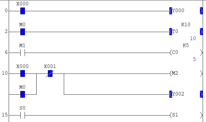
above is the example of out instructions
- in first rung output is depend on input X0 when X0 is ON than output Y000 is also ON.
- in second rung timer used as output instruction in in this example when input M0 change Off to ON than timer start increment until reached to preset value.
- in third rung counter device C0 used as output instruction, when M1 is change from Off to On than counter increment by value on every time.
- in fourth example multiple parallel output instruction used.
- in fifth Rung device S is used as input and output.
Mitsubishi Set Instructions
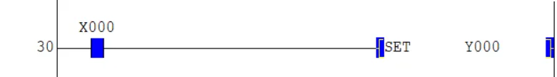
Mitsubishi Set Instructions sets a bit device permanently on. in set instruction only Y, M and S device is sets to permanently ON. Set instruction Only set ON to device. below is the example of Set instruction. in this example when X0 is set ON than set instruction executed and set a High bit(ON) to M1. now if the X0 Is change On to Off than M1 is still On this bit is set until M1 is not reset by reset instruction or power off in plc.
in second example we have a limit switch X002 as input when limit switch is operated it turn On M1 permanently and Y002 On until X002 is on.
Mitsubishi RST (Reset) Instructions
Mitsubishi RST (Reset) Instructions Resets timer, counter, coils, contacts and current values. These devices can all be reset at any time by driving the RST instruction. you can also reset bit which are set by Set instruction. below is the example of reset instruction in this instruction timer T1 Current value is reset to zero when reset input is set to on.
 Instructions.webp)
in second example of reset counter current value by rst instruction. when this instruction is executed counter C1 current value is set to zero and counter start counting from zero. you can also use this reset (RST) instruction to reset a bit which set by Set instruction.
Mitsubishi PLS Instructions
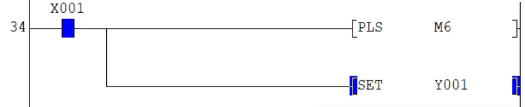
Mitsubishi PLS Instructions also Known as rising edge pulse instruction. a PLS instruction is executed, for one operation cycle after input signal has turned ON. below is the example of Mitsubishi PLS Instructions, in this example when X001 is set to High than only for one operation cycle M006 is operated.
Mitsubishi PLF Instructions
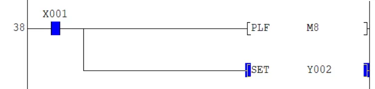
Mitsubishi PLF Instructions is also known as Falling / trailing edge pulse, it operates when a input signal has turned Off for one operation cycle. PLF instruction once executed in a operation cycle when input signal is turned off. below is the example off Mitsubishi PLF Instructions, in this example when input X001 is turned off than M008 is operated for only one operational cycle.
Both PLF and PLS instruction used for detection of falling and rising edge of input signal for one operational cycle. Y and M are only allowable device for these instruction you cannot use these instruction for any special relay like M8000. To hold a pulse rising edge or falling edge use set instruction to set On bit to device.
Mitsubishi INV Instructions
Mitsubishi INV Instructions is also known as Inverse Instructions. this Instructions Invert the current result of the internal PLC operations. this device not used any address you put this instruction where you want to invert result of operation. The INV instruction is used to change (invert) the logical state of the current ladder network at the inserted position.
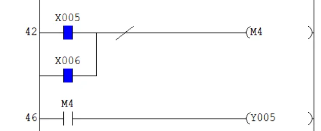
above is the example of Mitsubishi INV Instructions, in this example we have two input X005 and X006 to On M4. If we not use Invert instruction output Y005 is On when input X005 or X006 is ON, but here we use a invert signal so when both or any one input is On than output is OFF or if the Both inputs are Off than output is ON.