Transformer – Construction, Working Principle, Types, and Applications
Published on Aug 02, 2024 | Category: IntroductionShare this Page:
An electrical transformer transfer electrical energy from one circuit to another using the principle of electromagnetic induction. It plays a critical role in power systems by allowing voltage levels to be increased or decreased without changing the frequency. This ensures efficient power transmission over long distances and safe distribution at lower voltages.
This page provides a complete overview of transformers, including their working principle, main components, different types such as step-up, step-down, and isolation transformers, and their key applications in residential, commercial, and industrial sectors. Whether you're a student learning the basics or a professional looking to revise core concepts, this guide is designed to support your understanding of how transformers function in real-world electrical systems.
What is a Transformer?
A transformer works on the principle of electromagnetic induction. It transfers electrical energy from one circuit to another using a magnetic field, without any direct electrical connection between them and without changing the frequency.
The transformer can increase or decrease the voltage level depending on the requirement. It works on the principle of electromagnetic induction and helps in the safe and efficient transmission of electrical power.
Working Principle of a Transformer
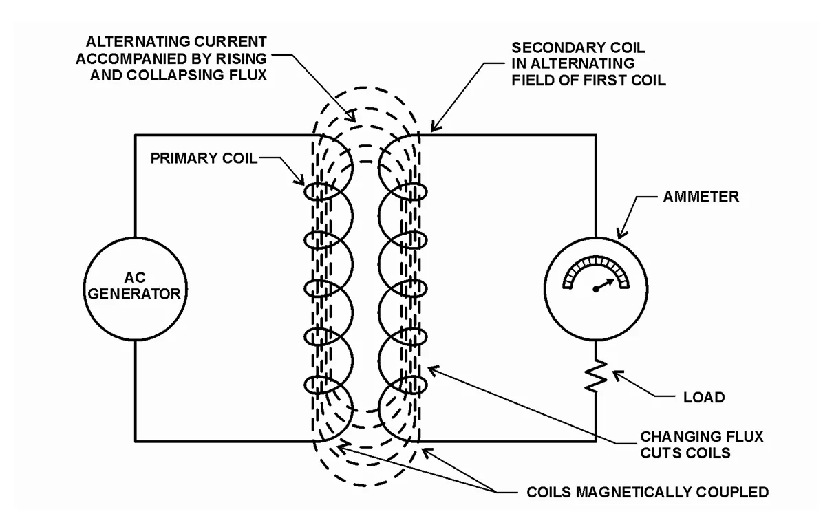
The working principle of a transformer is based on the concept of electromagnetic induction. When an alternating current (AC) flows through the primary winding (input coil), it creates a time-varying magnetic field around it. This changing magnetic field passes through the core and links to the secondary winding (output coil).
In its basic form, a transformer consists of two coils — the primary winding and the secondary winding — which are wound on a common magnetic core. These coils are electrically isolated but magnetically linked. When an alternating current (AC) flows through the primary winding, it creates a changing magnetic field (flux) in the core. This changing flux passes through the secondary winding and induces an electromotive force (EMF) as per Faraday’s Law of Electromagnetic Induction.
According to Faraday’s Law of Electromagnetic Induction, this varying magnetic flux induces an electromotive force (EMF) in the secondary winding. The magnitude of the induced voltage depends on the number of turns in the coils. If the secondary coil has more turns than the primary, the voltage increases (step-up transformer); if fewer, the voltage decreases (step-down transformer).
If the secondary winding is connected to a load, the induced EMF causes a current to flow, and electrical energy is transferred from the primary to the secondary circuit. The transformer can increase or decrease voltage levels depending on the number of turns in each coil, while the power remains nearly constant (ignoring losses).
In summary, a transformer is a device that:
- Transfers AC electrical energy from one circuit to another
- Operates on the principle of mutual induction
- Keeps the frequency constant during power transfer
- Uses a magnetic core to link the primary and secondary coils
- A transformer has no internal moving parts, and it transfers energy from one circuit to another by electromagnetic induction.
E.M.F. Equation of a Transformer
The E.M.F. (Electromotive Force) equation of a transformer shows the relationship between the induced voltage, frequency, number of turns, and magnetic flux in the transformer windings. It is based on Faraday’s Law of Electromagnetic Induction, which states that a changing magnetic flux induces an EMF in a coil.
Let:
- Φ = Maximum magnetic flux in the core (in Weber)
- f = Frequency of the AC supply (in Hz)
- Np = Number of turns in the primary winding
- Ns = Number of turns in the secondary winding
The RMS value of the induced EMF in each winding is given by:
Primary EMF (Ep) = 4.44 × f × Np × Φ
Secondary EMF (Es) = 4.44 × f × Ns × Φ
This equation shows that the induced EMF is directly proportional to the frequency, number of turns, and the maximum flux in the core. A higher number of turns or frequency results in a higher induced voltage.
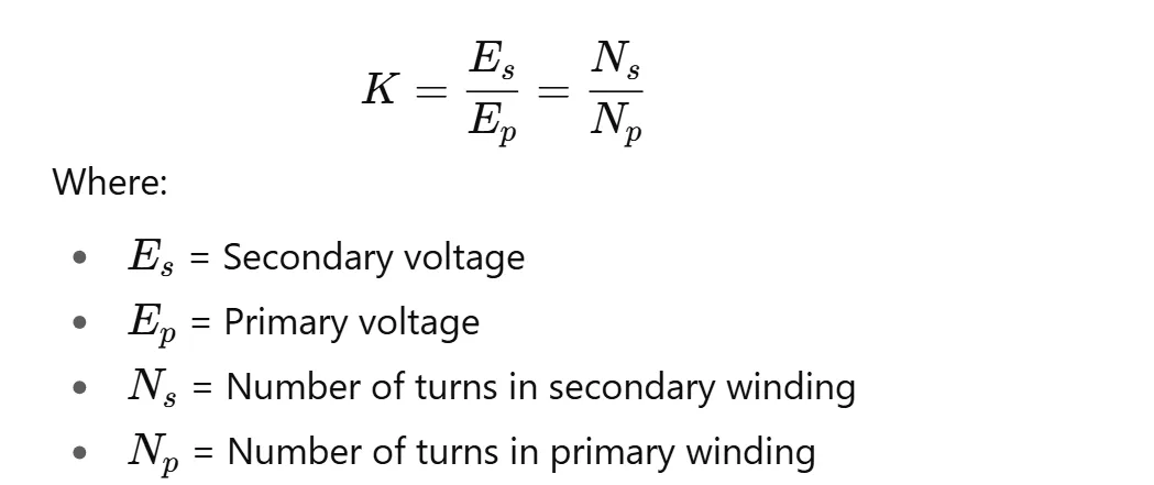
Voltage Transformation Ratio (K)
The voltage transformation ratio of a transformer, denoted as K, represents the ratio of the secondary voltage to the primary voltage. It is also equal to the ratio of the number of turns in the secondary winding to the number of turns in the primary winding.
Mathematically, it is expressed as:
Power Conservation in Ideal Transformer
In an ideal transformer, electrical power is conserved. That means the input power is equal to the output power (neglecting losses):

This implies that the current is inversely proportional to the voltage transformation ratio. So, if voltage increases, current decreases, and vice versa.
Transformer Voltage and Current
The voltage induced in a transformer's winding is proportional to the number of turns. If the secondary has more turns than the primary, voltage increases (step-up). If it has fewer turns, voltage decreases (step-down).
In a transformer, the voltage induced in each winding is directly proportional to the number of turns in that winding. This is the basic principle of electromagnetic induction.
- If the secondary winding has more turns than the primary, the transformer is a step-up transformer (voltage increases).
- If the secondary has fewer turns, it is a step-down transformer (voltage decreases).
Example:
If a transformer has:
- Primary voltage = 110V
- Primary turns (N₁) = 100
- Secondary turns (N₂) = 400
- Primary current = 20A
Then:
- Secondary voltage:
E₂ = (N₂ / N₁) × E₁ = (400 / 100) × 110 = 440V - Secondary current:
I₂ = (N₁ / N₂) × I₁ = (100 / 400) × 20 = 5A
Terminology:
Transformers are referred to as step-up or step-down based on whether the output voltage increases or decreases. However, in practice, it's more accurate to use:
- High-side – the higher voltage winding
- Low-side – the lower voltage winding
This avoids confusion in systems where power flow direction may reverse, such as inverters or regenerative drives.
Transformer Action
Transformer action is based on the principle of electromagnetic induction. When alternating current (AC) flows through the primary winding, it creates a changing magnetic field in the transformer core. This changing magnetic flux induces voltage in the secondary winding.
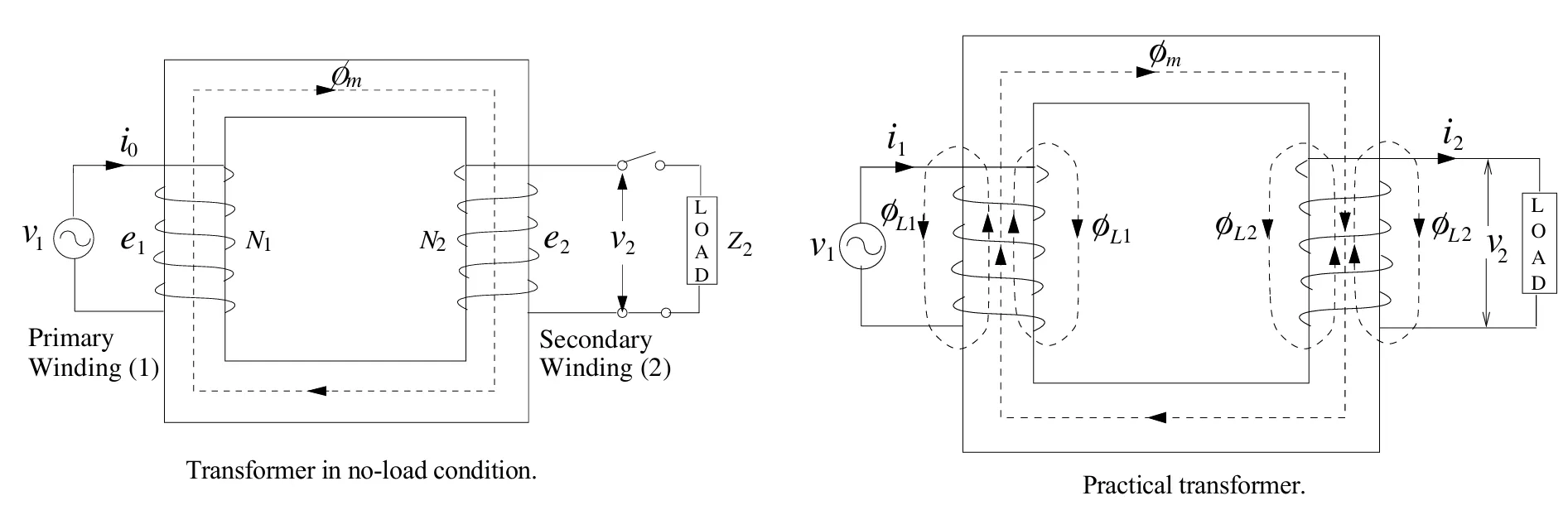
If the secondary is connected to a load, current flows through it. The voltage induced in the secondary depends on the number of turns in the coil. If the secondary has more turns than the primary, the transformer increases the voltage (step-up). If it has fewer turns, it decreases the voltage (step-down).
The primary and secondary windings are electrically isolated but magnetically linked. The amount of power delivered to the load is slightly less than the input due to internal losses. For efficient operation, the magnetic fields and power (volts × amps) in both windings must remain balanced.
The opposing magnetic fields created by the load current in the secondary affect the back EMF in the primary, which adjusts the primary current accordingly to maintain magnetic balance.
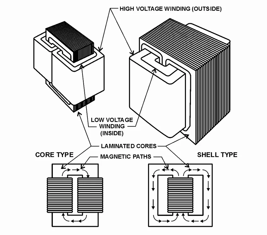
Core Type and Shell Type Transformers
Transformers are built using magnetic cores to help transfer electrical energy from one winding to another. Based on the arrangement of core and windings, transformers are mainly classified into two types: Core Type and Shell Type.
1. Core Type Transformer
In a core type transformer, the windings (coils) are placed around two vertical limbs of a rectangular magnetic core. The core surrounds the windings partially. This design is simple and commonly used in high-voltage applications.
- Windings are placed on both vertical limbs of the core.
- Low-voltage winding is placed close to the core, and high-voltage winding is wound over it.
- Magnetic flux flows through a single magnetic path.
- It is easy to cool and maintain.
- Commonly used in power and high-voltage transformers.
2. Shell Type Transformer
In a shell type transformer, the magnetic core completely surrounds the windings. Both the low and high-voltage windings are placed on the central limb, and the magnetic flux splits into two parallel paths in the outer limbs. This structure is compact and stronger mechanically.
- Windings are placed on the central limb of the core.
- Magnetic flux flows through two symmetrical paths in the outer limbs.
- Better mechanical strength and short-circuit performance.
- Used in distribution transformers, reactors, and large GSU (generator step-up) transformers.
Why Magnetic Core is Laminated
The core of a transformer is made of thin silicon steel sheets (laminations) to reduce energy losses. Since steel is a conductor, a changing magnetic field can induce unwanted currents called eddy currents inside the core, which cause heating and energy loss.
- Laminations reduce eddy current loss by increasing resistance to current flow inside the core.
- Each steel sheet is insulated from the next to prevent current flow across sheets.
- This design improves efficiency and reduces heat generation.
Losses in Transformer
In an ideal transformer, all input power would be transferred to the output. However, practical transformers experience certain losses. These losses primarily appear as heat and reduce the overall efficiency of the transformer. The two main types of losses are:
1. Core Losses (Iron Losses)
- Hysteresis Loss: Caused by the reversal of magnetic domains in the core material during each cycle of AC. It results in friction-like energy loss in the core, producing heat.
- Eddy Current Loss: Circulating currents induced within the iron core by changing magnetic fields also generate heat and energy loss.
Core losses occur as long as the primary winding is energized — even if no load is connected. They are constant and independent of the load. These losses significantly affect transformer lifespan. For every 8°C rise in core temperature, the life of insulation is halved.
2. Copper Losses (I²R Losses)
- These are caused by the resistance in the transformer windings (both primary and secondary).
- Copper losses vary with the load current and are proportional to the square of the current (I²R).
- Even at no-load, small losses occur due to magnetizing current in the primary winding.
Copper losses increase with the load, and they are dissipated as heat that must be removed by proper transformer cooling systems.
3. Stray Losses
These are small losses caused by leakage flux that induces eddy currents in nearby metallic parts like the transformer tank, clamps, etc.
4. Dielectric Losses
Occur in the insulation materials of the transformer when subjected to high voltages. These are generally small but important in high-voltage transformers.
Total Transformer Loss
Total Loss = Core Loss (constant) + Copper Loss (variable with load)
Minimizing Transformer Losses
- Using high-grade core materials (CRGO steel) to reduce hysteresis loss
- Laminating the core to reduce eddy currents
- Using thicker conductors to reduce winding resistance
- Designing for optimal cooling and ventilation
Core Losses and Leakage Flux
Some magnetic field lines do not follow the main path in the core and leak outside — this is called leakage flux. Shell type transformers control this better because the core provides a complete path for these stray flux lines, while core type transformers have higher leakage losses due to incomplete return paths.
Because of these advantages, shell type transformers are preferred in larger power systems where efficiency and mechanical strength are critical.
Types of Transformers
Transformers are classified based on construction, functionality, number of phases, and application. Below is a detailed categorization of common transformer types used in electrical systems.
1. Based on Construction
- Core Type Transformer – In this type, windings are placed around the two limbs of the magnetic core.
- Shell Type Transformer – In this design, the core surrounds the windings, offering better magnetic shielding.
2. Based on Function
- Step-Up Transformer – Increases voltage level from primary to secondary side. Commonly used in power transmission.
- Step-Down Transformer – Reduces voltage level and is typically used for domestic and industrial distribution.
3. Based on Number of Phases
- Single-Phase Transformer – Suitable for small power applications like homes and offices.
- Three-Phase Transformer – Used in industrial and high-power systems. More efficient than single-phase.
4. Based on Usage
- Power Transformer – Used in transmission networks, usually rated above 200 MVA.
- Distribution Transformer – Used in distribution networks, typically rated below 200 MVA.
- Instrument Transformer – Used to measure high voltage or current:
- Current Transformer (CT)
- Potential Transformer (PT)
- Isolation Transformer – Electrically isolates two circuits without changing voltage levels.
- Auto Transformer – Has a single winding that acts as both primary and secondary, more compact.
Why is Transformer Rating in kVA?
Transformers are rated in kVA instead of kW because:
- Copper loss depends on current.
- Iron (core) loss depends on voltage.
- Losses do not depend on power factor.
So, total loss depends on voltage × current = VA, not on kW.
That’s why transformer rating is given in:
- VA (Volt-Ampere) – for small transformers
- kVA (Kilovolt-Ampere) – 1000 VA
- MVA (Megavolt-Ampere) – 1,000,000 VA
Also, transformers are limited by heat. If the temperature goes above 100°C, the insulation gets damaged. So, better cooling and proper sizing increase life.
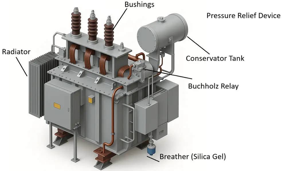
Main Parts of a Transformer (Classified)
1. Magnetic Circuit Parts
- Core: Made of laminated silicon steel. Provides a path for magnetic flux.
2. Electrical Circuit Parts
- Primary Winding: Connected to the input supply. Generates magnetic field.
- Secondary Winding: Delivers transformed voltage to the load.
- Tap Changer: Adjusts output voltage. May be:
- Off-Load Tap Changer (OLTC): Manual voltage adjustment when transformer is offline.
- On-Load Tap Changer: Automatic voltage regulation during operation.
3. Insulation and Cooling System
- Insulating Material: Paper, oil, or epoxy used to insulate windings and core.
- Cooling Oil (Transformer Oil): Acts as coolant and insulator.
- Radiator: Dissipates heat from oil into the air.
- Cooling Fans: Assist heat dissipation (in forced air-cooled transformers).
- Conservator Tank: Maintains oil level with thermal expansion.
- Breather (Silica Gel): Prevents moisture from entering conservator tank.
4. Protective Devices
- Buchholz Relay: Detects gas build-up due to internal faults in oil-filled transformers.
- Pressure Relief Device / Explosion Vent: Releases pressure in case of internal fault.
- Oil Level Gauge: Shows transformer oil level.
- Temperature Gauge / Thermometer: Measures oil and winding temperature.
5. External Terminals and Support
- Bushings: Insulated terminals for connecting external power lines to windings.
- Tank: Outer body that holds oil, windings, and core.
- Earthing Terminal: Ensures safe grounding of the transformer.
- Wheels / Rollers: Used to move the transformer if necessary.
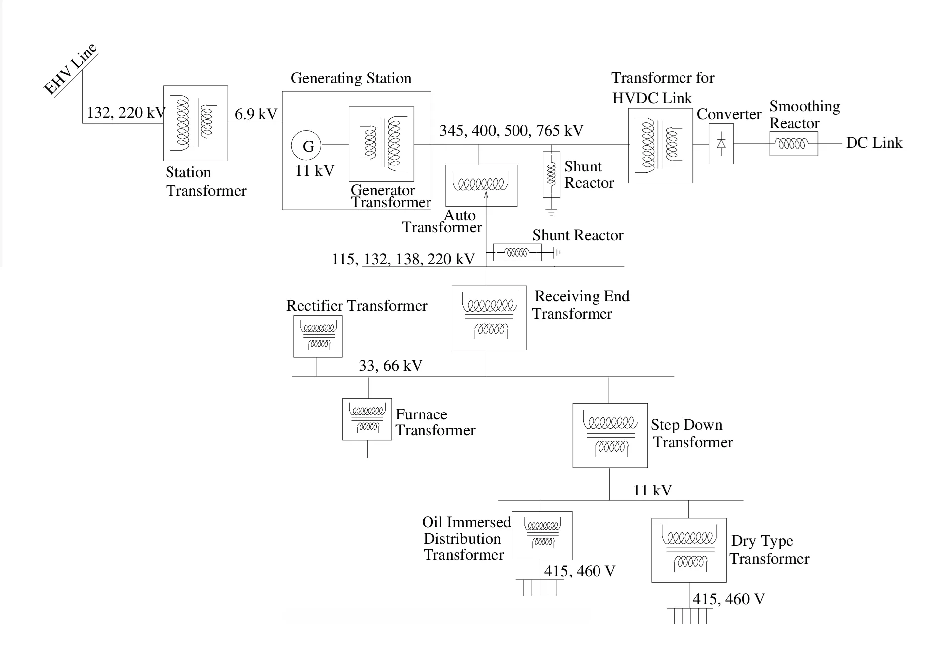
Applications of Transformers
1. Power Transmission and Distribution- Step-up transformers are used in power plants to increase voltage for long-distance transmission.
- Step-down transformers are used at substations to reduce voltage for safe domestic and industrial use.
- Used in TVs, computers, chargers, and audio systems to match voltage levels.
- Isolation transformers provide safety by electrically isolating devices from the power source.
- Used in welding machines, furnaces, and control panels for specific voltage needs.
- Auto-transformers are used in motors for soft starting and speed control.
- Current Transformers (CTs) and Potential Transformers (PTs) are used in metering and protection relays.
- Used in solar and wind power plants to integrate generated power into the grid.
- Used to convert grid voltage to suitable levels for train traction systems.