What is Radar Level Transmitter (RLT)? Working, Applications, Wiring & Analog Signal
Published on July 4, 2024 | Category: introductionShare this Page:
a level transmitter is a instruments which we use in in industry to measure level like tank, eater, open cahnael close chanel etc. where a rada level transmitter commonly known as RLT is used to measure levle by useinf radar technology. rlt ia non contact bascic use to measure levle. it is use beacsue have property like maximumn range, low intefarace affection, accuracy of result. a rlat is availavle in 2 wire, 4 wire wire, 3 wire . in this page we undestand basicn worlking orincple, connection diagram ir rlt to plc., scaling of rlt wtc. This page provides a complete overview of Radar Level Transmitters (RLT) used in process industries for accurate level measurement in tanks, silos, and vessels. It explains the working principle, types (contact & non-contact), wiring details, analog output, advantages, and common industrial applications. Ideal for instrumentation engineers, automation technicians, and interview preparation.
What is Radar Level Transmitter (RLT)?
A Radar Level Transmitter (RLT) measures the level of a material (usually liquid or solid) inside a tank using radar signals. The transmitter is mounted on the top of the tank and sends out high-frequency electromagnetic waves from its antenna toward the product surface.
When these radar waves hit the surface of the material, they are reflected back to the transmitter. The transmitted and reflected signals differ slightly in frequency because the radar uses a method called FMCW (Frequency Modulated Continuous Wave). The frequency difference is directly related to the distance between the antenna and the product surface.
By mixing the transmitted and received signals, a low-frequency signal is produced, which can be measured precisely. This allows for highly accurate, fast, and reliable level measurement even in challenging process environments.
Measuring Principle of Radar Level Transmitter (RLT)
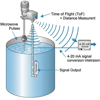
Radar Level Transmitters (RLT) operate based on the time delay of radar pulses reflected from the product surface. The transmitter, installed on top of the tank, emits a radar signal toward the surface of the liquid or solid. When the pulse hits the surface, it reflects back to the sensor.
The device measures the time taken for the pulse to return and calculates the distance. This time-of-flight measurement is then converted into a level reading. The level is determined from the reference point (datum) to the product surface.
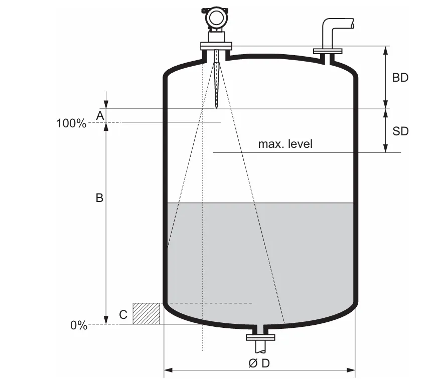
Key Measurement Parameters
- A - Range Set: The maximum measurable range from the sensor to the lowest product level.
- B - Low Adjustment (Zero Point): The distance from the sensor to the 0% level mark (typically bottom of the tank).
- C - High Adjustment (100% Point): The reference for full level or maximum usable tank height.
- D - Blind Area (Dead Zone): The top zone of the tank where radar signals cannot detect product levels accurately. The product should not reach into this zone.
Datum Reference:
Measurement begins at the mechanical installation point — either the bottom of the screw thread or the flange sealing surface.
Important Note:
Ensure that the liquid surface never enters the blind zone at the top. This would result in inaccurate or failed measurements.
Output of Radar Level Transmitter
Radar Level Transmitters typically provide a **4–20 mA analog signal output**, which is proportional to the level of the product in the tank. This output can be connected directly to a PLC, DCS, SCADA, or any industrial controller for monitoring and control purposes.
In modern radar transmitters, additional communication protocols may also be available:
- 4–20 mA + HART Protocol: Allows signal and configuration data over the same wires.
- Modbus, PROFIBUS, FOUNDATION Fieldbus: For digital communication with advanced diagnostics.
- Wireless Output (optional): Available in IoT or remote monitoring applications.
Typical Output Mapping:
- 4 mA → Tank Empty (0%)
- 20 mA → Tank Full (100%)
Advantages of Radar Level Transmitter
Radar Level Transmitters offer numerous advantages over traditional level measurement technologies like ultrasonic, float-based, or capacitance types.
- Non-contact measurement: Ideal for corrosive, hot, or hazardous materials.
- High accuracy: Even in the presence of dust, vapor, pressure, and temperature variations.
- Maintenance-free: No moving parts means reduced wear and long-term stability.
- Suitable for any media: Works well with solids, liquids, slurry, foam, and vapors.
- Long measuring range: Some models measure up to 100 meters.
- Works in extreme environments: Handles high-pressure and high-temperature conditions.
- Supports smart communication: Integration with HART, Modbus, PROFIBUS, or wireless networks.
Application of Radar Level Transmitter
Radar Level Transmitters (RLTs) are widely used in industrial process control for accurate, reliable, and continuous level measurement. Due to their non-contact measurement capability and resistance to harsh environments, they are ideal for a variety of challenging applications.
- Oil and Gas Industry: Used for level monitoring in crude oil storage tanks, LPG tanks, and chemical separators where pressure and temperature are high.
- Water and Wastewater Treatment: For level control in reservoirs, sludge tanks, and open channel flow measurement.
- Chemical and Petrochemical Plants: Ideal for aggressive, corrosive, or high-vapor tanks such as acid, solvent, and polymer vessels.
- Food and Beverage Industry: Used in hygienic tanks for milk, juice, syrup, and beverage level monitoring under sanitary conditions.
- Power Plants: Steam drum and condensate tank level measurement in boiler and turbine systems.
- Pharmaceutical Manufacturing: Accurate level control in sterile and clean-in-place (CIP) environments.
- Mining and Bulk Solids: Measurement in silos containing ore, powders, or granules.
- Marine and Shipbuilding: Ballast tank and fuel tank level monitoring under dynamic motion conditions.
Measuring Range of Radar Level Transmitter
The effective or usable measuring range of a Radar Level Transmitter (RLT) is influenced by several factors and may vary based on installation conditions and product properties. Understanding these parameters ensures accurate and reliable level measurement.
Key Factors Affecting Measuring Range:
- Antenna Size: Larger antennas can emit stronger signals with narrower beam angles, which improves detection range and accuracy, especially in tall tanks.
- Reflectivity of the Medium: Materials with higher dielectric constants (like water or acids) reflect radar signals better, resulting in more reliable measurements. Low dielectric materials (like oil or hydrocarbons) reduce the effective measuring range.
- Mounting Location: Ideal mounting should be at the center of the tank or away from inlets, agitators, or wall obstructions. Poor mounting may cause signal reflections and errors.
- Interference Reflections: Internal structures like mixers, ladders, or nozzle flanges may cause false echoes, limiting the usable range. Most modern RLTs have echo mapping or false signal suppression to mitigate this.
Note: The measuring range is also affected by the radar frequency (e.g., 6 GHz, 26 GHz, 80 GHz). Higher frequencies provide better resolution but may have reduced penetration in certain materials or vapors.
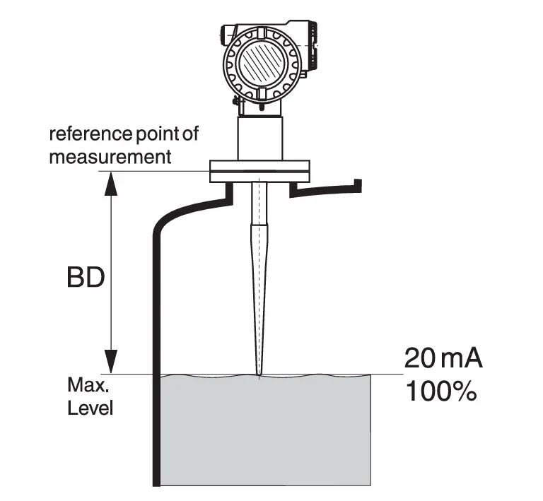
Blocking Distance (BD) in Radar Level Transmitters
The Blocking Distance (BD) is the minimum zone directly beneath the radar level transmitter's antenna (typically from the mounting flange) where reliable measurement is not possible. It is also known as the dead zone or blind zone.
Radar signals within the blocking distance are affected by internal reflections and hardware limitations, making level readings in this zone inaccurate or unreliable. Therefore, the maximum liquid level should always remain below the BD line.
Key Parameters:
- BD (Blocking Distance): Measured from the reference point — usually the sealing surface of the mounting flange.
- Typical BD Values:
- Free-space radar in storage tanks: 390 mm to 540 mm (approx. 15" to 21").
- Values vary depending on the antenna size, frequency, and model of the radar device.
- Recommendation: Ensure that the tank's maximum fill level is always lower than the BD to avoid signal interference or false high-level alarms.
Note: Blocking distance may be configurable in some smart radar models, and some offer auto-adjustment or alert if the product enters the blind zone.
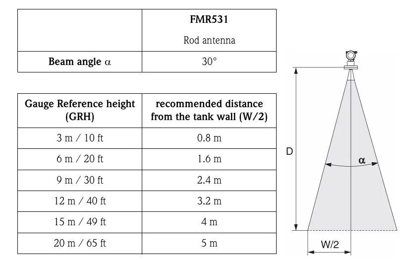
Beam Angle of Radar Level Transmitter
The beam angle (denoted as α) of a radar level transmitter defines how wide the radar signal spreads as it travels from the antenna into the tank. It is the angle at which the energy density of the radar waves drops to half of its peak value (–3 dB point). This beam is shaped like a cone and is most concentrated along the centerline.
Microwave energy is also emitted outside the central beam and may reflect off tank walls, agitators, or nozzles, potentially causing false echoes if not properly installed or configured.
Beamwidth Diameter (W):
The diameter of the radar beam at a certain measuring distance (D) is determined by the beam angle (α) and the type of antenna used. This relationship can be approximated as:
Beamwidth (W) ≈ 2 × D × tan(α / 2)
Example:
- For a beam angle of 10° at a measuring distance of 10 meters:
- W ≈ 2 × 10 × tan(5°) ≈ 1.75 meters
Smaller beam angles (e.g., 4–6°) are desirable for tall, narrow tanks or for measuring through nozzles. Wider beam angles (e.g., 15–20°) are more suitable for short, wide tanks but require a clearer measurement path.
2-Wire Radar Level Transmitter Wiring Diagram with PLC
In a 2-wire radar level transmitter, the same two wires are used to provide power to the device and carry the analog output signal (usually 4–20 mA). It is commonly loop-powered and connected directly to a PLC analog input module.
- Wiring:
- +24V DC to Radar Transmitter (+ terminal)
- Radar Transmitter (– terminal) to PLC Analog Input (+)
- PLC Analog Input (–) back to power supply (–)
- Advantages: Simple and cost-effective wiring.

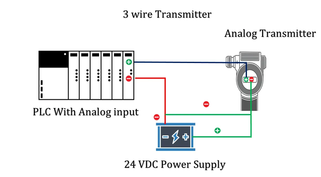
3-Wire Radar Level Transmitter Wiring Diagram with PLC
A 3-wire radar transmitter uses separate wires for power and output signal. It requires:
- One wire for +24V DC supply
- One wire for 0V or ground
- One separate wire for 4–20 mA signal output to the PLC
This configuration helps in reducing signal noise and improving measurement accuracy, especially over longer cable runs.
- Wiring:
- +24V DC to Radar Transmitter Power (+)
- 0V DC (ground) to Radar Transmitter Power (–)
- Signal OUT (4–20 mA) to PLC Analog Input (+)
- PLC Analog Input (–) to ground
4-Wire Radar Level Transmitter Wiring Diagram with PLC
In a 4-wire radar transmitter, the power supply and analog output signal are fully isolated and handled on separate circuits. It is typically used when electrical isolation or signal integrity is critical.
- Two wires for +24V DC power supply (Power + and Power –)
- Two separate wires for the analog signal (Signal + and Signal –)
This setup is ideal for applications where electrical noise is present or strict galvanic isolation is required.
- Wiring:
- Power + to Transmitter Power +
- Power – to Transmitter Power –
- Signal + to PLC Analog Input (+)
- Signal – to PLC Analog Input (–)
What is Frequency Range in Radar Level Transmitters?
Radar Level Transmitters (RLTs) operate using microwave frequency bands to determine the level of a substance in a tank or vessel. The frequency range directly impacts the radar's resolution, penetration ability, and sensitivity to tank geometry and internal disturbances.
Types of Radar Level Transmitters by Frequency:
- C-Band Radar (6 GHz): Used for solids or rough surfaces, wide beam angle.
- X-Band Radar (10 GHz): Balance between penetration and resolution, good for liquids.
- K-Band Radar (24–26 GHz): Standard for most industrial applications, good accuracy and stability.
- W-Band Radar (80 GHz): Latest generation, narrow beam, excellent performance in small nozzles or tall, narrow tanks.
Why Frequency Matters:
Low-frequency radar (like 6 GHz) is better at penetrating vapor, foam, and dust but requires larger antennas. High-frequency radar (80 GHz) offers better resolution and narrower beam angles, making it ideal for space-constrained installations or tanks with internal obstructions.

How to Scale Analog Signals in Any PLC
Application:
Scaling is required to convert analog input values (e.g., 4–20 mA or 0–10V) into meaningful engineering units such as pressure, level, temperature, or speed.
Step-by-Step Procedure:
1. Read Raw Analog Input
Read the digital raw value from the analog input module.
- Example: Siemens S7-300 → Range: 0 to 27648
- Example: Allen-Bradley → Range: 0 to 32767
- Example: Delta → Range: 0 to 4095
2. Determine Raw Signal Range
Find the digital values corresponding to your signal range.
- For 4–20 mA: 4 mA = Raw_Min, 20 mA = Raw_Max
- Use the analog module manual to get exact values
3. Identify Engineering Range
Know the physical range you want to scale to.
- Example: 0 to 10 meters
- Example: 0 to 100°C
- Example: 0 to 100 bar
4. Apply Scaling Formula
Use the standard scaling equation:
Scaled_Value = ((Raw_Value - Raw_Min) / (Raw_Max - Raw_Min)) × (Eng_Max - Eng_Min) + Eng_Min
5. Store or Display Result
Store the scaled value in a REAL or FLOAT register and use it in the PLC logic or display it on an HMI.
Flowchart of Analog Signal Scaling

Flowchart: Scaling Analog Inpult in PLC
Summary:
- Raw Range: As per analog module (e.g., 5530 to 27648)
- Engineering Range: As per physical unit (e.g., 0 to 10 m)
- Scaled Output: Real-world units used in logic or HMI