What is LVDT (Linear Variable Differential Transformer)? Working, Types, Models & Top Manufacturers
Published on aug 04, 2024 | Category: introductionShare this Page:
The Linear Variable Differential Transformer (LVDT) is a highly accurate, contactless position sensor used to measure linear displacement. Its design allows for smooth and frictionless operation, making it ideal for harsh and high-precision environments.
LVDTs are widely adopted across various industries including aerospace, subsea systems, industrial automation, power generation, and laboratory-grade test setups. Their ability to operate reliably under extreme conditions, while delivering repeatable and noise-resistant output signals, makes them the preferred choice for both static and dynamic position monitoring.
This page provides a complete guide to how LVDTs function, their internal construction, different types available, typical models, and key manufacturers. It also helps engineers and technicians make informed choices when selecting the right LVDT for their applications.
What is LVDT (Linear Variable Differential Transformer)?
The Linear Variable Differential Transformer, or LVDT, is a precision electromechanical sensor used to measure linear displacement. It converts the linear motion of an object into a proportional electrical signal, allowing accurate and repeatable position measurement without any physical contact between moving parts.
LVDTs are widely known for their high resolution, infinite mechanical life, and reliability in extreme environments. They can detect minute displacements ranging from a few microns to several inches, with typical measurement ranges extending up to ±30 inches (±0.762 meters). This makes them ideal for aerospace, industrial automation, materials testing, and subsea systems.
Construction of LVDT (Linear Variable Differential Transformer)
The LVDT consists of a cylindrical structure that houses a coil assembly and a movable magnetic core. It is designed to accurately measure linear displacement by converting mechanical motion into electrical signals.
Coil Assembly: The coil system includes a primary winding placed between two symmetrically located secondary windings. All coils are wound on a single, hollow tube made of thermally stable, glass-reinforced polymer. This assembly is moisture-resistant and shielded using a high-permeability magnetic layer. The entire unit is enclosed in a stainless steel housing for durability and stability.
Magnetic Core: A separate soft iron or magnetically permeable core, called the armature, moves freely inside the hollow bore of the coil assembly. This core is mechanically connected to the object whose position needs to be measured. There is no physical contact between the core and the coil bore, allowing frictionless operation and long service life.

Working Principle of LVDT
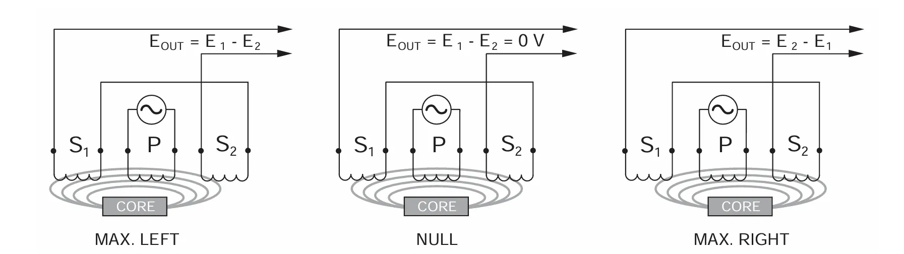
The Linear Variable Differential Transformer (LVDT) is energized by applying an alternating current (AC) source to the primary winding (P). This AC current produces a magnetic flux, which is transferred to two symmetrically spaced secondary windings (S1 and S2) via a movable ferromagnetic core.
At the central or null position—when the core is exactly midway between S1 and S2—the magnetic flux is evenly distributed, inducing equal voltages E1 and E2 in both secondary windings. Since these voltages are 180 degrees out of phase, the differential output voltage (E1 - E2) is essentially zero.
When the core moves toward winding S1, the magnetic flux coupled to S1 increases while it decreases in S2. This results in E1 > E2, and the differential voltage (E1 - E2) becomes positive. Conversely, if the core moves toward S2, then E2 > E1, and the output becomes negative, indicating both magnitude and direction of the displacement.
The output is a linear function of the core's displacement over a defined range. This makes LVDTs highly accurate for position measurement in automation, aerospace, and industrial applications.
Types of LVDT (Linear Variable Differential Transformer)
LVDTs come in several variations depending on the application, mounting configuration, environmental conditions, and signal conditioning requirements. Although the working principle remains the same, their construction and specifications may differ. Below are the common types of LVDTs:
- Unguided Armature Type: In this type, the core (armature) is not physically attached or guided by bearings. It is ideal for dynamic applications where frictionless movement is crucial.
- Captive Armature Type: The armature is guided within low-friction bearings and is attached to a spring return mechanism or external device. It is suitable for controlled linear motion.
- Spring-Loaded LVDT: Contains an internal spring that returns the armature to a default position. These are commonly used in gauging applications where the sensor must automatically retract.
- Submersible LVDT: Specially sealed for underwater or corrosive environments like subsea operations, oil exploration, or hydraulic applications.
- High-Temperature LVDT: Designed with materials and insulation that can withstand elevated temperatures (often up to 200°C or more).
- Miniature or Micro LVDT: Compact sensors used for fine-position measurements in aerospace, medical instruments, or micro-robotics.
Each type of LVDT is selected based on factors such as accuracy, environment, size constraints, and the required mechanical interface. Selecting the right LVDT ensures optimal performance and longevity.
Applications of LVDT (Linear Variable Differential Transformer)
LVDTs are widely used in industries that require accurate and reliable linear position or displacement measurement. Due to their non-contact operation, durability, and high resolution, LVDTs are suitable for harsh environments and precision systems alike. Below are common application areas:
- Industrial Automation: For position feedback in actuators, valves, and robotic arms.
- Aerospace: Used in landing gear position sensing, flight control systems, and vibration analysis.
- Power Generation: Monitoring turbine valve positions, steam valve control, and pressure control feedback.
- Hydraulic & Pneumatic Systems: LVDTs track piston position and fluid control in hydraulic cylinders.
- Subsea & Marine Applications: Pressure-sealed LVDTs are deployed in subsea valves and underwater drilling equipment.
- Material Testing Machines: To measure deformation, strain, or tensile movement during stress tests.
- Railway & Transportation: Track displacement sensors and wheel positioning systems.
- Medical Devices: Compact LVDTs are used in MRI-compatible instruments and robotic surgery systems.
From micro-scale precision in medical systems to rugged environments in power plants and offshore rigs, LVDTs offer versatility and reliability across many engineering domains.
Wire Color of LVDT
LVDT sensors are equipped with multiple wires for excitation input, signal output, and sometimes shielding or grounding. Understanding the color coding of these wires is crucial for proper installation, connection to signal conditioners, and ensuring accurate measurements.
Typically, the Red wire is used for the positive excitation input (+EXC), while the Black wire is for the negative excitation input (−EXC). The output signal from the secondary windings is commonly carried by a Green wire (S1 or Output +) and a White wire (S2 or Output −). In many industrial LVDTs, an additional bare or braided shield wire is provided for grounding and noise shielding purposes, especially in environments with electrical interference.
Although these wire colors are widely adopted, it's important to always verify the specific wiring diagram provided in the manufacturer's datasheet, as variations may exist between different models or brands.

Advantages and Disadvantages of LVDT
The Linear Variable Differential Transformer (LVDT) is widely preferred for position measurement due to its non-contact operation, excellent repeatability, and durability. One major advantage is that the moving core does not physically touch the coil structure, minimizing wear and enabling long-term, maintenance-free operation. LVDTs also provide infinite resolution and high sensitivity, making them ideal for detecting even the smallest displacements. Their robust construction allows them to function reliably in harsh environments, including subsea, nuclear, and aerospace applications.
However, LVDTs do come with certain disadvantages. They require an AC excitation source and signal conditioning electronics, which adds to system complexity. Additionally, they are sensitive to stray magnetic fields and temperature variations, which may affect accuracy unless properly shielded or compensated. The initial cost of LVDT sensors may also be higher compared to simpler contact-based devices, though the long-term reliability often outweighs the upfront investment.
Calibration of LVDT
Calibration of a Linear Variable Differential Transformer (LVDT) is essential to ensure accurate position measurements across its operating range. The process involves correlating the electrical output of the LVDT to known physical displacements so that the sensor provides a reliable and repeatable response. Typically, this is done using a precision micrometer or displacement stage to move the core incrementally while recording the corresponding output voltage.
During calibration, the LVDT’s output is measured at various known positions—often starting from the null point (zero displacement). A graph is plotted with core displacement on the x-axis and the corresponding LVDT output voltage on the y-axis. This helps determine linearity, sensitivity (slope), and zero offset. Calibration can be done manually or using automated systems, and results are often used to develop scaling factors in data acquisition software or PLC logic. It’s important to repeat the calibration periodically, especially in critical applications, to maintain measurement integrity.
Troubleshooting of LVDT
Troubleshooting an LVDT (Linear Variable Differential Transformer) involves identifying and resolving issues that affect its accuracy, output signal, or response. Common problems include signal distortion, incorrect calibration, mechanical misalignment, or electrical faults. A systematic approach helps ensure the sensor performs reliably in position-sensing applications.
First, check the excitation voltage — it must match the LVDT’s specified AC input (typically 1–10 kHz). If the excitation is missing or unstable, the output will be incorrect or absent. Next, inspect the wiring: loose or swapped secondary wires can affect polarity or cause phase shift errors. Mechanical misalignment of the core can cause non-linearity or friction, especially if the core rubs against the bore. Noise in the output signal may indicate shielding issues or electrical interference. Also verify the signal conditioning circuit or controller input settings.
Using a signal simulator or known reference position can help verify the LVDT and electronics independently. If the issue persists, consider recalibrating the system or replacing damaged components. Proper grounding, shielding, and avoiding sharp bends in the wiring also improve LVDT reliability.
Output of LVDT in Terms of Voltage and Current
The Linear Variable Differential Transformer (LVDT) provides an electrical output signal based on the position of its movable core. This output is usually in the form of an AC voltage, which can be further processed into DC voltage or current for industrial applications.
Voltage Output of LVDT
- The raw output of an LVDT is a differential AC voltage between two secondary windings.
- At the null (center) position, the output voltage is ideally zero:
Vout = E1 - E2 = 0 - As the core moves, the difference between E1 and E2 changes:
Vout = E1 - E2 - The output voltage is linearly proportional to the core's displacement within a certain range.
- Typical AC output range: ±1 V to ±5 V AC (rms)
Current Output of LVDT (After Signal Conditioning)
- LVDT outputs are often converted using signal conditioning electronics.
- Standard industrial output: 4–20 mA current loop
-
Meaning of current range:
- 4 mA → Minimum core displacement
- 20 mA → Maximum core displacement
- Current output is ideal for long-distance transmission and noise immunity.
Summary Table
- Raw AC Voltage: ±1 V to ±5 V (used in short distance or test systems)
- Conditioned DC Voltage: 0–10 V or ±10 V (for PLCs, analog inputs)
- Conditioned Current Output: 4–20 mA (widely used in industrial automation)
prescription drugs from canada
May 14, 2026, 7:45 amI all the time used to study post in news papers but now as I am a user of web thus from now I am using net for articles or reviews, thanks to web.