What is a VFD and how does it work?
Published on Mar13, 2023 | Category: basicvariable frequency drive (VFD), A motor drive which are used to control controls the speed, torque, direction of a motor by varying frequency of input power. VFD run an AC motor at variable speeds or let them ramp up their speed to give them a smooth startup. VFD first converts supply AC input into DC than it filter DC with a capacitors than it will convert the DC into AC. VFD used for controlling speed of belt conveyor belt, fan, blower, pump, compressors etc. motor reduced energy consumption and increase efficiency of system. VFD easily communicate with PLC so easy to monitor and control motor. vfd protect our motor from phase difference, under voltage, over-voltage, overload, high current, low current etc. VFDs are used in low and medium voltage AC-AC and DC-AC system. VFD have some following property -
What is the benefit of VFD?
what is a Working Principle of Variable Frequency Drive (VFD) ?
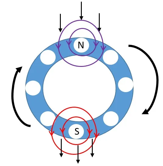
The synchronous speed of the motor is given by Synchronous speed = (120 x frequency) / number of poles. so Synchronous speed of a motor depends on the frequency and number of poles. consider a 4-pole motor powered by a 60 Hz AC supply so synchronous speed of motor is (120 x 60) / 4 = 1,800 RPM. as we know that due to slip and load of the motor actual speed of motor will be slightly lower than the synchronous speed. so speed of the shaft given by
.webp)
if we want to adjust speed of motor we have first option to change the number of poles, but this is a physical change of motor. It would require rewinding, and result in a step change to the speed. second option to change frequency of supply input voltage. VFD use same thing for varying speed of motor.
How Drive Changes Motor Speed
pole of the motor is constant speed can be varied adjusting frequency. basically vfd use Pulse width modulation to change frequency. vfd basic working diagram shown below. for controlling frequency vfd have 3 stage first conversion of 3 phase ac supply into dc. in second phase filter of rectified output third stage inverter stage where dc converted into ac in pulse form.
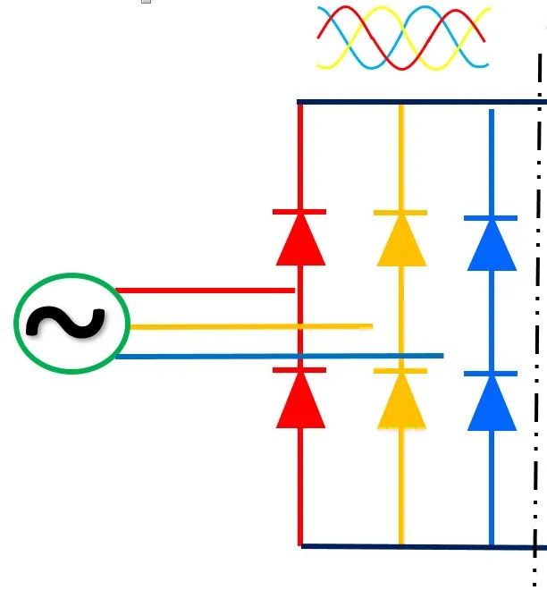
rectifier stage of VFD
The input section of the drive is the rectifier. six diodes, arranged in an electrical bridge. These diodes convert AC power to DC power. Two rectifiers are required for each phase of power. Since most large power supplies are three phase, there will be a minimum of 6 rectifiers used (see Figure 2). Appropriately, the term “6 pulse” is used to describe a drive with 6 rectifiers.
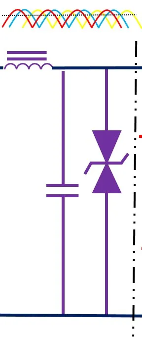
DC bus/Filter stage of VFD
in this stage fixed DC voltage achieved from rectified output voltage. Output power of rectifiers is stored on a dc bus. The DC Bus/filters filter and smooth’s waveform. for 460 VAC an average dc bus voltage is 650V to 680V.You can calculate this as line voltage times 1.414.The inductor (L) and the capacitor (C) work together to filter out any AC component of the DC waveform. The smoother the DC waveform, the cleaner the output waveform from the drive.
invertor stage of VFD
invertor stage of VFD this is final stage of vfd. in this section DC voltage converted into ac voltage. But, it does so in a variable voltage and frequency output. Insulated Gate Bipolar Transistor (IGBT) is mainly used in modern VFDs.The IGBT uses pulse width modulation (PWM) to simulate a current sine wave at the desired frequency to the motor. Insulated Gate Bipolar Transistors (IGBTs) to switch the DC bus on and off at specific intervals. In doing so, the inverter actually creates a variable AC voltage and frequency output.
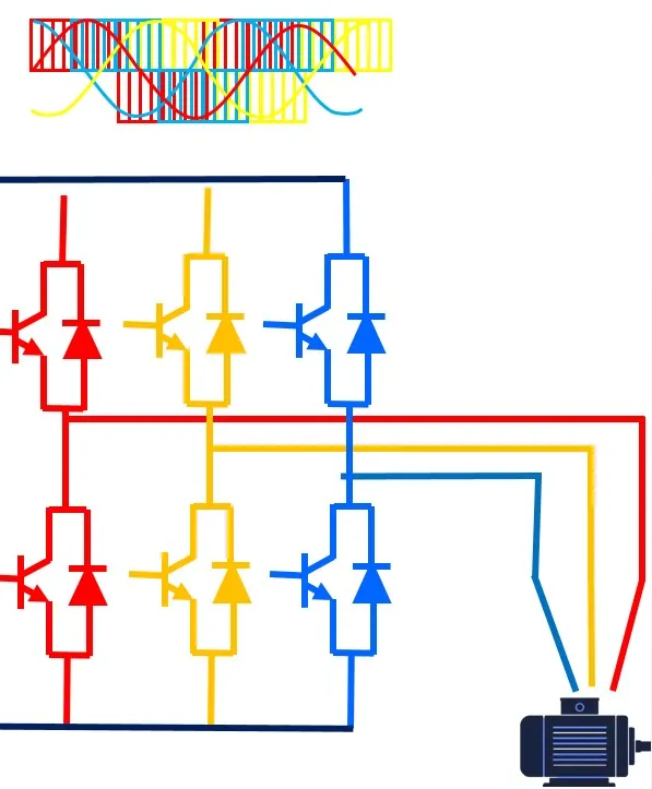
output waveform of VFD
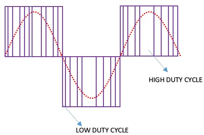
the output of the VFD are doesn’t provide an exact AC input sine waveform. Instead, it provides voltage pulses that are at a constant magnitude. The drive’s control board signals the power device’s control circuits to turn “on” the waveform positive half or negative half of the power device. This alternating of positive and negative switches recreates the 3 phase output. The longer the power device remains on, the higher the output voltage. The less time the power device is on, the lower the output voltage . Conversely, the longer the power device is off, the lower the output frequency. The speed at which power devices switch on and off is the carrier frequency, also known as the switch frequency. The higher the switch frequency, the more resolution each PWM pulse contains.in vfd switch frequencies for IGBT are 3KHz to 4KHz and for SCR 250 to 500 times per second. higher the switch frequency gives the smoother output waveform and the higher.
why use IGBT IN VFD?
output of VFD voltage and frequency depends. Depends on what kind of power devices your drive uses like transistor, SCR or IGBT. Bipolar Transistor technology (BJT) began superseding SCRs in drives in the mid-1970s. In the early 1990s, those gave way to using Insulated Gate Bipolar Transistor (IGBT) technology. The SCR output depends on how soon in the control cycle that gate turns on. The IGBT output also depends the length of time the gate is on. However, it can turn off anytime in the control cycle, providing a more precise output waveform. IGBTs also require a control circuit connected to the gate, but this circuitry is less complex and doesn’t require a reversal of polarity. Thus, you would approach troubleshooting differently if you have an SCR-based drive. An SCR contains a control element called a gate. The gate acts as the “turn-on” switch that allows the device to fully conduct voltage. The device conducts voltage until the polarity of the device reverses-and then it automatically ‘turns off.” Special circuitry, usually requiring another circuit board and associated wiring, controls this switching
Sunday
January 2, 2026, 11:59 amCan I get a pdf of this kindly?
Thanks.