What is the 4-20 mA Signal in PLC? Working, Application, and Benefits
Published on Jun26, 2025 | Category: IntrodunctionShare this Page:
The 4-20 mA signal is the most commonly used analog signal standard in industrial automation and PLC systems. It plays a critical role in transmitting data from field instruments such as level transmitters, RTDs, thermocouples, gas analyzers, pressure transmitters, and flow sensors to a PLC’s analog input module. Introduced in the 1950s alongside the rise of electronic control systems, the 4-20 mA current loop quickly became a dominant method for analog communication due to its simplicity, reliability, and noise immunity. In a 4-20 mA loop, 4 mA typically represents 0% of the measured process variable, while 20 mA represents 100%. The 4 mA baseline not only allows the signal to power loop-powered devices but also helps detect faults such as broken wires or sensor failures—something not possible with 0-10V signals. Compared to voltage signals, the 4-20 mA loop performs better over long distances and is less affected by electrical noise or voltage drops. This makes it ideal for harsh industrial environments. The signal is transmitted as a constant current through all components in series: the transmitter, power supply, and PLC analog input card. As the process variable changes, the current varies proportionally, and the PLC converts this analog current into a digital value for monitoring or control. The simplicity of installation, built-in fault detection, and ability to power the sensor itself make the 4-20 mA signal a preferred choice in process control systems. Despite its widespread use, many professionals still lack a fundamental understanding of how the 4-20 mA loop works. Learning this concept is essential for anyone working with automation, PLCs, or industrial instrumentation.
What is 4 to 20 mA in PLC?
The 4 to 20 mA signal is a type of analog signal used in PLC systems to send data from field devices like sensors and transmitters to the PLC. It works by sending a small electric current, starting from 4 milliamps (mA) up to 20 milliamps, depending on the value being measured, such as temperature, pressure, or level. For example, 4 mA usually means 0% of the measurement, and 20 mA means 100%. This type of signal is reliable, can travel long distances without losing accuracy, and is not easily affected by electrical noise. That’s why it is commonly used in industries for process control and automation.
Why is the 4 to 20 mA signal used in Instrumentation?
- Reliable over long distances: Current signals do not drop like voltage signals, making them ideal for remote sensor locations.
- Noise resistant: Less affected by electrical interference, which is common in industrial environments.
- Fault detection: The minimum signal starts at 4 mA, so a signal below that indicates a broken wire or device failure.
- Simple wiring: A 2-wire loop can transmit both power and signal, reducing wiring complexity and cost.
- Standardized range: Most instruments and PLCs are designed to work with the 4 to 20 mA standard, ensuring compatibility.
- Power for field devices: Loop-powered transmitters can operate using the same current signal, eliminating the need for an external power supply.
What is the Maximum Distance for a 4-20 mA Signal?
The maximum distance for a 4-20 mA signal depends on several factors such as the wire size (gauge), power supply voltage, and the total resistance in the loop. There is no fixed maximum distance for a 4-20 mA signal. It depends on three main things:
- The voltage of the power supply (usually 24V DC)
- The resistance of the receiving device (like a PLC or analog input module)
- The resistance of the copper wire used in the loop
According to Ohm’s Law: R = V / I = 24V / 0.10A = 240 ohms. So, your loop can have up to 240 ohms of total resistance when 100 mA current is used.
If your PLC analog input has an input resistance of 100 ohms, then the wire can have up to:
240 - 100 = 140 ohms of allowable wire resistance.
The distance depends on the wire size. Thicker wires (lower resistance) allow the signal to travel farther.
| Wire Size (AWG) | Resistance per 1000 feet |
|---|---|
| 22 AWG | 19.0 ohms |
| 20 AWG | 11.9 ohms |
| 18 AWG | 7.51 ohms |
| 16 AWG | 4.73 ohms |
| 14 AWG | 2.97 ohms |
| 12 AWG | 1.87 ohms |
For example, with 20 AWG wire (approx. 12 ohms per 1000 feet), you can run the loop up to:
140 ÷ 12 ≈ 11.6 × 1000 = 11,600 feet (around 3.5 km), under ideal conditions.
Always consider extra safety margin for real-world factors like connector resistance, environmental conditions, and voltage drop in the transmitter. Shorter and thicker cables provide better performance.
What is the principle of 4-20mA?
The principle of 4-20 mA is based on using a small electric current to represent a range of values from a sensor or transmitter. In this system, 4 mA represents the minimum value (0%) and 20 mA represents the maximum value (100%) of a measured signal, such as temperature, pressure, or level. As the process value changes, the current changes proportionally. This current loop allows reliable and noise-resistant transmission of analog signals over long distances. The 4 mA starting point also helps detect wire breaks or device failures, which would drop the signal below 4 mA and trigger a fault.
Why 4-20 mA is used instead of 0-20 mA?
The 4-20 mA signal is used instead of 0-20 mA because it provides better safety, reliability, and fault detection. When the signal starts at 4 mA (instead of 0 mA), it allows the system to detect problems like a broken wire or a failed sensor. If the signal drops below 4 mA, it clearly indicates a fault. In contrast, with 0-20 mA, a 0 mA reading could mean either a valid 0% value or a wiring issue, making it harder to troubleshoot. Additionally, the 4 mA base current can be used to power loop-powered devices like transmitters, reducing the need for separate power wiring. This makes the 4-20 mA standard more efficient and reliable for industrial applications.
4-20 mA Transmitter and PLC Analog Input Example
A 4-20 mA transmitter converts a physical value, like temperature or pressure, into a current signal. This signal is sent to a PLC analog input (AI) module, which reads the current and converts it into a digital value for processing or display.
For example, a pressure transmitter is set to measure from 0 to 10 bar. At 0 bar, it sends 4 mA to the PLC, and at 10 bar, it sends 20 mA. If the pressure is 5 bar (50%), the transmitter outputs 12 mA. The PLC reads this current and calculates the actual pressure based on scaling.
The wiring is usually simple: the transmitter is powered by a 24V DC supply, and the current loop passes through the transmitter and into the analog input channel of the PLC. This setup ensures accurate and noise-resistant signal transmission, even over long distances.
4-20 mA Current Loop in PLC – Analog Signal Connection
The 4-20 mA current loop is a common method to connect field transmitters to PLC analog inputs. It allows the transfer of analog signals, like temperature, pressure, or level, using electrical current. The loop typically includes a 24V DC power supply, a 2-wire transmitter, and a PLC analog input module.
In a standard setup, the positive terminal of the 24V power supply connects to the transmitter. The transmitter regulates the current based on the measured value and sends it through the loop to the analog input of the PLC. The PLC reads the current (between 4 mA and 20 mA) and converts it into engineering values using scaling.
This loop is highly reliable because the current remains constant even over long distances, and it is less affected by electrical noise compared to voltage signals.
Types of 4-20 mA Wiring
The 4-20 mA current loop can be implemented in different wiring schemes depending on the power and signal requirements. The common types are:
- 2-Wire System
- 3-Wire System
- 4-Wire System
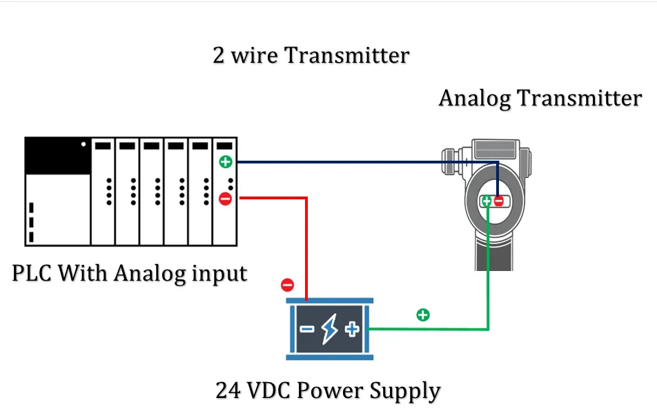
What is Two-Wire 4-20 mA Signal?
In a 2-wire configuration, the transmitter is powered by the same two wires that carry the 4-20 mA signal. This is known as a loop-powered device.
- Only two wires: signal + power combined.
- Used for low-power field instruments.
- Simplified wiring, ideal for remote or hazardous locations.
Connection: Power supply → (+) Transmitter → PLC Analog Input → (–) Power Supply.
How do you connect a 2-wire transmitter to a PLC?
A 2-wire transmitter gets both power and transmits the signal using the same two wires. The power supply positive (+) connects to the transmitter’s + terminal, and the - terminal connects to the PLC analog input. The power supply’s negative (-) is connected to the PLC common (GND). This forms a complete loop for the 4-20 mA current signal.
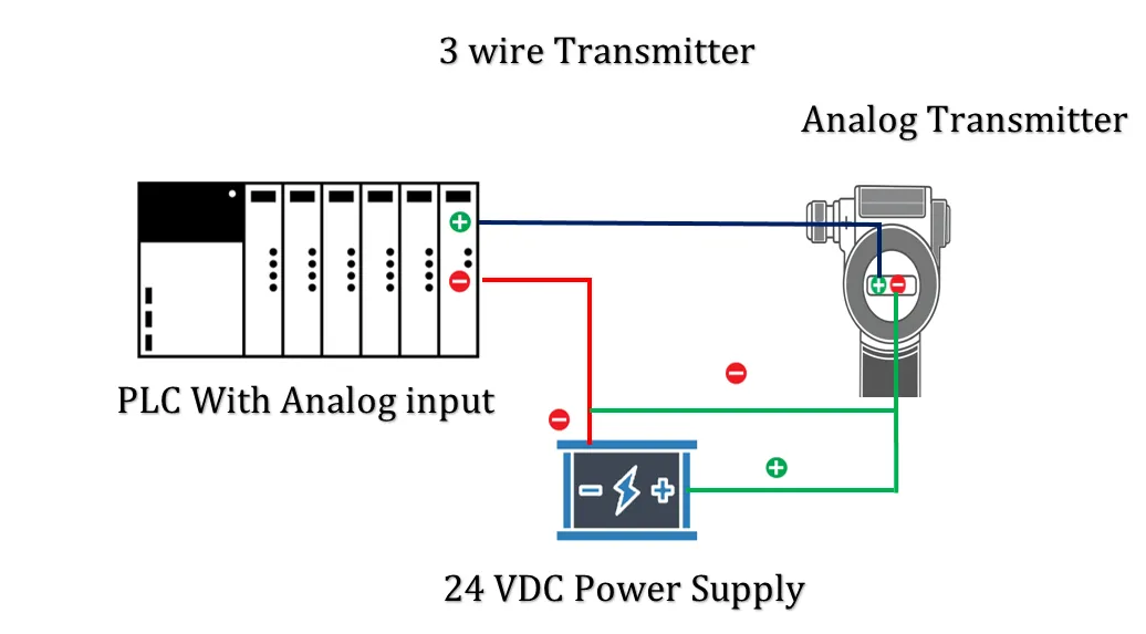
What is Three-Wire 4-20 mA Signal?
In a 3-wire system, the transmitter has a dedicated ground wire and separate wires for power and signal. It provides a compromise between simplicity and power capacity.
- Three wires: +24V DC, GND (common), and 4-20 mA output.
- Transmitter is powered via two wires (V+ and GND), and the signal goes through a separate wire.
- Used where higher power than 2-wire is needed, but 4-wire is not necessary.
Connection: V+ and GND go to the transmitter for power, while signal (4-20 mA) goes from transmitter to PLC analog input.
How do you connect a 3-wire transmitter to a PLC?
In a 3-wire transmitter setup, the transmitter has a separate power line and signal line. The positive of the power supply goes to the transmitter’s + terminal, the negative goes to the PLC and transmitter common (GND). The signal output from the transmitter (typically marked as + signal) goes to the PLC analog input.
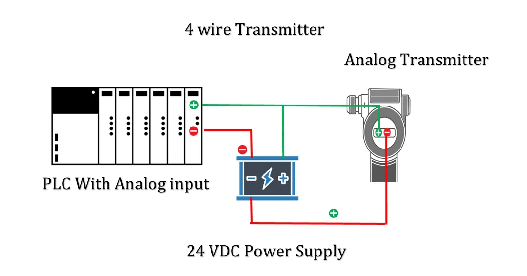
What is Four-Wire 4-20 mA Signal?
In a 4-wire configuration, the transmitter has completely separate pairs of wires for power and signal. These are usually active devices (self-powered).
How do you connect a 4-wire transmitter to a PLC?
A 4-wire transmitter uses a separate power source and signal circuit. The transmitter is powered by its own supply (AC or DC). The current signal loop is formed between the transmitter signal output and the PLC analog input. This provides better isolation and is used in cases where noise immunity or higher power is needed.
4-20 mA Loop Troubleshooting
The 4-20 mA current loop is a reliable method for analog signal transmission, but faults can occur due to wiring, component failure, or calibration issues. Proper troubleshooting helps identify and fix these problems quickly to restore system functionality.
Common Symptoms of 4-20 mA Loop Problems
- Loop current stuck at 0 mA, 4 mA, or 20 mA
- PLC/Controller shows no input or out-of-range value
- Fluctuating or unstable readings
- Incorrect values despite correct process conditions
- High loop resistance or broken signal
Step-by-Step Troubleshooting Guide
- Check Power Supply: Ensure 24V DC supply is available and connected properly.
- Inspect Wiring: Look for broken wires, loose terminals, corrosion, or wrong connections.
- Measure Loop Current: Use a multimeter in series mode to measure loop current (should be between 4-20 mA).
- Bypass Transmitter: Simulate signal with a loop calibrator to isolate transmitter issues.
- Verify Load Resistance: Ensure total loop resistance (wiring + input resistance) is within acceptable range (typically < 600 ohms).
- Test Loop Continuity: Use a continuity tester to check for open circuits or short circuits.
- Inspect Grounding: Check for ground loops or improper grounding causing noise or errors.
- Check Transmitter Settings: Make sure the range, span, and power mode (2-wire or 4-wire) are correct.
Common 4-20 mA Loop Faults and Solutions
| Problem | Possible Cause | Solution |
|---|---|---|
| 0 mA Reading | Open loop, no power, blown fuse | Check power supply and wiring continuity |
| Stuck at 4 mA | Sensor reading is at minimum range | Verify process variable and sensor health |
| Stuck at 20 mA | Sensor at maximum range or short circuit | Check sensor calibration and input conditions |
| Random Noise or Fluctuation | Electrical interference, ground loop | Shield cables, correct grounding, isolate noise source |
| Incorrect PLC Value | PLC scaling error or broken analog input | Reconfigure scaling in software or test PLC input |
Tips for Maintaining a Healthy Loop
- Use shielded twisted pair cables for long runs
- Label wires and connections for easy identification
- Use proper grounding techniques to avoid interference
- Perform periodic loop checks using a loop calibrator or simulator
How to Connect 4-20 mA Sensor to PLC
Connecting a 4-20 mA sensor to a PLC allows you to measure analog signals such as temperature, pressure, or level. The connection depends on whether the sensor is a 2-wire, 3-wire, or 4-wire type and whether the PLC analog input is current-sinking (passive) or current-sourcing (active).
Basic Components Required
- 4-20 mA sensor/transmitter (2-wire, 3-wire, or 4-wire)
- PLC with analog input module (current input type)
- 24V DC power supply
- Wiring (typically shielded twisted pair)
Wiring a 2-Wire 4-20 mA Sensor to PLC (Loop-Powered)
- Connect the positive terminal of the 24V power supply to the + terminal of the sensor.
- Connect the – terminal of the sensor to the + terminal of the PLC analog input (AI+).
- Connect the – terminal of the PLC analog input (AI–) to the – terminal of the power supply.
Wiring Diagram (Text Description)
+24V DC  ─────► [Sensor +]
                   [Sensor –] ─────► [PLC AI+]
                                      [PLC AI–] ─────► 0V (GND)
Wiring a 3-Wire 4-20 mA Sensor to PLC
- Connect 24V DC to V+ and GND to GND of the sensor.
- The third wire (signal output) connects to the PLC AI+ (analog input).
- Connect AI– of the PLC to GND (common ground).
Wiring a 4-Wire 4-20 mA Sensor to PLC
- Power the sensor using a separate 24V DC supply (V+ and GND).
- Sensor output terminals (usually marked OUT+ and OUT– or Loop+ and Loop–) connect directly to the PLC’s AI+ and AI–.
- Ensure both power and signal grounds are properly isolated to avoid ground loops.
Important Considerations
- Check Sensor Type: Know if your sensor is 2-wire, 3-wire, or 4-wire.
- Use Correct PLC Input: Ensure the analog input supports 4-20 mA current.
- Loop Resistance: Total resistance in the loop should be below sensor’s load limit.
- Shielding: Use shielded cable and ground only one end to reduce noise.
PLC Analog Input Configuration
- Set analog input type to "Current" mode (4-20 mA).
- Scale input in software to convert 4-20 mA to real-world engineering units (e.g., 0–100°C).
- Perform loop testing using a simulator or multimeter.
What is a 4 to 20 mA Sensor Connection?
A 4 to 20 mA sensor connection is a standard method of transmitting analog signals in industrial control systems. The sensor converts physical values (like temperature, pressure, or level) into a current signal ranging from 4 mA (minimum value) to 20 mA (maximum value).
- 4 mA: Represents the lowest measurable value (zero or minimum process condition)
- 20 mA: Represents the highest measurable value (full-scale process condition)
- 0 mA: Indicates a fault or open circuit (used as diagnostic)
These sensors can be powered in 2-wire, 3-wire, or 4-wire configurations depending on the power and signal requirements.
PLC Analog Wiring – 4-20 mA PLC Wiring Examples with Diagram
PLC analog input modules can read current signals like 4-20 mA. The wiring depends on the sensor type and input module configuration.
2-Wire Sensor to PLC Analog Input (Passive Input)
+24V ───► Sensor +
Sensor – ───► PLC AI+
PLC AI– ───► 0V (Power Supply GND)
3-Wire Sensor to PLC
+24V ───► Sensor V+
0V ───► Sensor GND and PLC AI–
Sensor OUT ───► PLC AI+
4-Wire Sensor to PLC
Sensor Power: +24V and 0V (GND)
Sensor Output: Loop+ ─► PLC AI+
               Loop– ─► PLC AI–
Note: Always check your PLC analog input specification (active/passive input, isolation, scaling range) before wiring.
4-20 mA Signal Advantages in Industrial Control
The 4-20 mA current loop is a preferred standard for analog signal transmission in process automation because of its many advantages:
- Noise Immunity: Less affected by electrical noise compared to voltage signals.
- Long Distance Transmission: Can transmit signals over hundreds of meters without loss.
- Open-Circuit Detection: 0 mA can indicate a broken wire or device fault.
- Linear Signal: Current varies linearly with the measured value for easy scaling.
- Loop Power Capability: 2-wire devices can be loop-powered, reducing wiring needs.
Difference Between 0-10V and 4-20 mA in PLC
| Parameter | 0-10V Signal | 4-20 mA Signal |
|---|---|---|
| Signal Type | Voltage | Current |
| Noise Susceptibility | High | Low |
| Transmission Distance | Short (<20 m) | Long (>300 m) |
| Signal Loss Over Distance | Voltage drops with wire resistance | Current remains consistent |
| Fault Detection | Hard to detect open circuit | 0 mA can indicate broken wire |
| Powering Devices | Cannot power loop | Can power 2-wire devices |
| PLC Input Module Type | Analog Voltage Input | Analog Current Input |