What is Analog Signal in PLC? | Types of Analog Signals Used in Automation
Published on Jun26, 2025 | Category: IntrodunctionShare this Page:
PLC networks are designed to transfer data from one point to another, and during this transmission, the data exists as electromagnetic signals. Understanding the nature of data and signals is fundamental before diving into advanced concepts of data communication. One such type is the analog signal, which is a time-varying, continuous signal that can represent an infinite number of values within a defined range. Analog signals convey information using variations in physical properties such as voltage, current, or frequency through a medium—typically electrical wiring. These signals are widely used to represent naturally occurring phenomena like temperature, pressure, sound, and light. Unlike digital signals that represent discrete values, analog signals fluctuate smoothly and continuously over time. A classic example of an analog signal is the sine wave, which flows fluidly from one value to another, passing through an infinite number of intermediate values. This fundamental understanding of analog signals is essential in PLC systems where accurate measurement and control of real-world variables are required.
What is an Analog Signal in PLC?
Analog signals in PLC systems are used to represent real-world, continuously varying phenomena such as temperature, pressure, level, or flow. Unlike discrete (digital) signals that have only two states—ON or OFF—analog signals can take on an infinite number of values within a defined range. This makes them ideal for measuring variables that change smoothly over time.
Analog input modules in PLCs are specifically designed to interface with field devices that output continuous signals. For example, a temperature sensor may produce a signal that gradually changes based on environmental conditions. These analog signals are typically in the form of voltage (e.g., 0–10V) or current (e.g., 4–20mA) and are converted by the PLC's analog input module into digital values that the controller can interpret and use in control logic.
Because analog signals reflect fine changes in a physical parameter, they allow for precise monitoring and control in automation systems. Applications include process control in manufacturing, HVAC systems, water treatment plants, and more—anywhere that accurate measurement of variable conditions is essential.
What is an Analog Input Signal in PLC?
An analog input signal in a PLC refers to a continuous voltage or current signal that is converted into a digital value for processing. This allows the PLC to interpret real-world variables such as temperature, pressure, level, or flow. A wide range of sensors are available that convert physical parameters into electrical signals—typically voltage (e.g., 0–10V) or current (e.g., 4–20mA). The analog input module reads these signals and converts them into digital data, which the PLC can then process. This data can be logged, used in calculations, sent via email or network, or used to make real-time control decisions.
What is an Analog Output Signal in PLC?
An analog output signal in a PLC is a continuous electrical signal (voltage or current) generated by the PLC based on digital data. The analog output module converts digital values into corresponding variable voltages (e.g., 0–10V) or currents (e.g., 4–20mA) that are sent to field devices. These outputs are typically used to control devices such as variable frequency drives (VFDs), actuators, control valves, or dimmable lighting. By using analog outputs, a PLC can provide fine control over physical processes such as motor speed, temperature regulation, or fluid flow.
Types of Analog Signal in PLC
Analog signals used in PLCs represent real-world, continuous values and can vary over a range rather than being limited to just ON or OFF states. These signals are essential for monitoring and controlling variables like temperature, pressure, speed, and flow in industrial processes. The main types of analog signals in PLC systems include:
- Current Signal (4–20 mA or 0–20 mA):
- Voltage Signal (0–10 V, 1–5 V, or ±10 V):
- Resistance Signal (RTD – e.g., Pt100):
- Millivolt Signal (Thermocouples):
- Frequency Signal:
Each type of analog signal serves specific sensor types and applications. The choice depends on signal range, noise immunity, accuracy requirements, and transmission distance.
4–20 mA and 0–20 mA Current Signal in PLC
Current signals like 4–20 mA and 0–20 mA are the most widely used analog input types in PLC systems. The 4–20 mA signal is preferred for industrial applications due to its ability to detect wiring faults—any reading below 4 mA typically indicates a disconnection or failure. These signals are ideal for transmitting sensor data over long distances without significant signal loss and are commonly used for measuring temperature, pressure, flow, and level.
0–10V, 1–5V, ±10V Voltage Signal in PLC
Voltage signals are another popular analog signal type used in PLCs, especially for short-distance applications. The 0–10V and 1–5V signals represent a linear scale of process values, while ±10V signals are used in motion control systems for bi-directional operation. Although voltage signals are easy to use and widely supported, they are more prone to signal degradation due to electrical noise or voltage drops over longer cable runs.
RTD (Resistance Temperature Detector) Signal in PLC
RTDs (Resistance Temperature Detectors), such as the Pt100, provide analog signals based on resistance changes in response to temperature. These resistance signals are converted into voltage or current signals through signal conditioners before being read by the PLC. RTDs are known for their high accuracy and repeatability, making them ideal for precise temperature monitoring in industrial automation systems.
Thermocouple Millivolt Signal in PLC
Thermocouples generate millivolt-level analog signals based on temperature differences between two dissimilar metals. These signals are very small and require amplification and cold junction compensation before they can be processed by a PLC. Thermocouples are commonly used in high-temperature industrial applications due to their wide operating range, affordability, and durability.
Frequency Signal as Analog Input in PLC
Frequency signals represent analog values using variations in frequency (pulses per second). Commonly used in flow meters and speed sensors, frequency inputs are ideal for measuring rate-based values. High-speed counter modules in PLCs detect these pulses and convert them into accurate process values such as RPM, fluid flow rate, or conveyor speed.
what is 4–20 mA Current Signal
The 4–20 mA current signal is the most widely used analog signal in industrial automation. It represents a linear scale where 4 mA typically indicates the minimum value (0%) and 20 mA indicates the maximum value (100%) of a measured process variable such as temperature, pressure, or flow. This signal is highly reliable for long-distance transmission and is immune to electrical noise. One of its key advantages is fault detection—any signal below 4 mA can indicate a wiring issue or sensor failure.
what is 0–20 mA Current Signal
The 0–20 mA current signal functions similarly to the 4–20 mA signal but starts from zero. It is used in older or less critical systems where open-circuit detection is not required. Although it provides the full range from 0% to 100%, it lacks the ability to detect a wire break, making it slightly less secure than 4–20 mA in mission-critical applications.
what is 0–10 V Voltage Signal
The 0–10 V analog signal is a standard voltage range used in many automation and control systems. A 0 V signal represents the minimum measurement, and 10 V represents the maximum. Voltage signals are easy to interface with and are ideal for short-distance applications. However, they are more prone to signal degradation due to voltage drops or electrical noise, especially over long cable runs.
what is 1–5 V Voltage Signal
The 1–5 V signal range is an older analog voltage standard that still exists in many legacy systems. Like 0–10 V, it represents a continuous signal for varying process values, with 1 V as the minimum and 5 V as the maximum. Its primary benefit is lower voltage operation, but it has largely been replaced by the 0–10 V standard in modern systems.
what is ±10 V Bipolar Voltage Signal
The ±10 V analog signal is a bipolar voltage signal used in specialized control applications, particularly in motion control systems such as servo drives. This signal allows both positive and negative values, enabling the PLC to control the direction as well as the magnitude of an output, such as forward/reverse motor control. It provides greater flexibility in applications requiring symmetrical operation around a zero point.
How PLC Processes Analog Signals
A PLC (Programmable Logic Controller) processes analog signals using specialized analog input and output modules. These signals represent real-world variables like temperature, pressure, and flow, which vary continuously rather than in discrete ON/OFF states.
When a sensor sends an analog signal (such as 4–20 mA or 0–10 V) to the PLC, the analog input module first converts this signal into a digital value using an Analog-to-Digital Converter (ADC). The PLC then interprets the digital data and uses it in its control logic—for example, to monitor fluid levels or adjust motor speed.
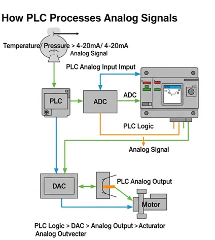
If the PLC needs to control an analog device, it sends a digital signal to an analog output module, which converts it into a continuous voltage or current using a Digital-to-Analog Converter (DAC). This output can then control devices such as variable speed drives, control valves, or analog meters.
This continuous input-output process allows PLCs to accurately monitor and control physical processes, making them essential in industries such as manufacturing, water treatment, HVAC, and energy systems.