Limit Switch – Types, Working Principle and Applications
Published on July 11, 2024 | Category: IntroShare this Page:
A limit switch is an electromechanical device used to detect the presence or position of an object by making or breaking an electrical connection when a specific mechanical limit is reached. These devices are widely used in industrial automation and machinery control systems due to their reliable, consistent, and maintenance-free operation across a broad range of applications. Over the decades, limit switches have proven to be dependable components, offering accurate performance in both normal and extreme environments—hot or cold, indoor or outdoor. Despite advances in electronic sensor technology, limit switches continue to outperform alternatives by providing mechanical simplicity, long service life, and precise data feedback. To maintain global industry standards, modern limit switches are continually improved for enhanced durability and reduced operational downtime. Their straightforward design, adaptability, and robust construction make them essential in position detection, safety interlocks, machine controls, and other motion-based systems.
What is a Limit Switch?
A limit switch is a type of sensor that responds to physical contact with a moving object to control electrical circuits. It is commonly used to monitor the motion or final position of machine components, ensuring operations proceed safely and accurately. When activated by a mechanical force, the switch changes its state—either initiating or stopping an electrical signal. These devices play a vital role in automation, machine control, and process safety.
To withstand tough working conditions, limit switches are housed in protective enclosures that guard against exposure to liquids, dust, extreme temperatures, and mechanical stress. This rugged design makes them well-suited for environments like manufacturing plants, outdoor installations, and heavy industrial equipment where durability is critical. They help reduce equipment failure, minimize maintenance, and extend the operational life of machinery.
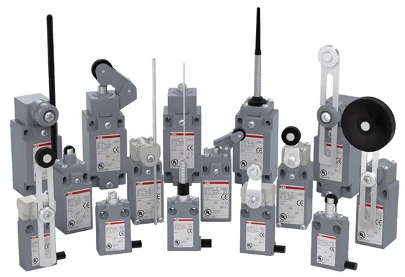
Limit switches come in a variety of formats, including side-mounted (horizontal), top-mounted (vertical), and multi-directional types. Each variant serves different installation needs and mechanical configurations. Internally, a typical limit switch includes several key elements that work together to detect movement and relay electrical signals, helping to maintain smooth and safe operations in automated systems.
Their adaptability makes limit switches a practical choice in applications ranging from conveyor tracking to lift systems and machine guarding. By selecting the appropriate actuator style—such as a lever arm, roller, or plunger—engineers can tailor the switch to meet specific control or sensing requirements. Their simplicity, reliability, and versatility continue to make them an essential component in electrical and mechanical systems.
Limit Switch Operation: Working Mechanism and Electrical Switching
A limit switch is a type of electromechanical sensor that operates through physical contact between its actuator (plunger, roller, or lever) and a moving object. When the target object reaches a defined position and presses the actuator, it causes a mechanical movement that toggles the internal electrical contacts. This toggle is known as reaching the operating point.
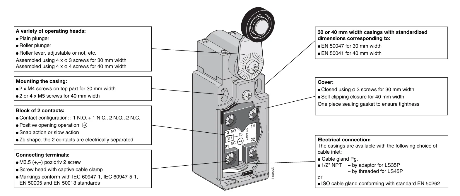
The uploaded diagram illustrates a roller-lever type limit switch and highlights its internal and external components including contact blocks, mounting options, casing sizes, and connection terminals.
How the Electrical Contacts Work
Inside the switch, there are mechanical contacts that change state depending on actuator position:
- Normally Closed (NC) Contact: This contact remains closed in its default (unpressed) state, allowing current to flow. When the actuator is pressed, the NC contact opens and stops the current.
- Normally Open (NO) Contact: This contact remains open by default and closes when the actuator is pressed, allowing current to pass through.
The transition of contacts is typically accompanied by a tactile “click” due to the snap-action mechanism inside. This makes it easy to detect switch activation both physically and electrically.
Key Features Highlighted in the Diagram
- Operating Heads: Includes plain plunger, roller plunger, and roller levers (adjustable or fixed), easily replaceable depending on application requirements.
- Contact Block: Comes with multiple configurations like 1 NO + 1 NC or 2 NO / 2 NC, allowing flexible control logic.
- Zb Contact Shape: Indicates that contacts are electrically isolated from each other.
- Cover and Casing: Available in 30 mm and 40 mm widths with IP-rated sealing gaskets for dust and water protection.
- Electrical Connections: Supports various cable inlets including Pg gland, ISO gland, and ½" NPT thread, compliant with international standards (EN 50041, EN 50047).
- Mounting Flexibility: The switch can be mounted using M4 or M5 screws based on body size, ensuring robust attachment to panels or machines.
Applications and Benefits
Limit switches are used in a wide range of applications such as position sensing in conveyor systems, door interlocks, end-of-travel detection in actuators, and machine safety. Their mechanical reliability, ability to switch high currents, and straightforward operation make them ideal for both industrial and commercial environments.
By using standard-compliant, rugged enclosures and multiple actuation styles, limit switches continue to be a preferred solution for mechanical sensing in automation systems.
What are the Main Components of a Limit Switch?
Limit switches offer excellent precision, both in terms of accuracy and repeatability. This high level of reliability is primarily due to their direct physical contact with the target object. When an object touches the limit switch actuator, such as a lever or plunger, it causes the actuator to move a short distance known as the pre-travel. Once it reaches the designated operating point, the internal contacts are triggered to open or close the circuit. If the actuator continues to move beyond this point, the additional movement is referred to as over-travel, which ensures the switch functions reliably even with slight overshooting.
Limit switches are engineered for consistent performance and typically include several key components. These parts may be integrated into a single compact unit or designed in a modular format for easier replacement and customization. The major elements include the actuator (lever or plunger), internal switch mechanism, housing or enclosure, terminal connections, and sealing features for environmental protection. These elements work together to ensure dependable operation across a wide range of industrial and mechanical systems.
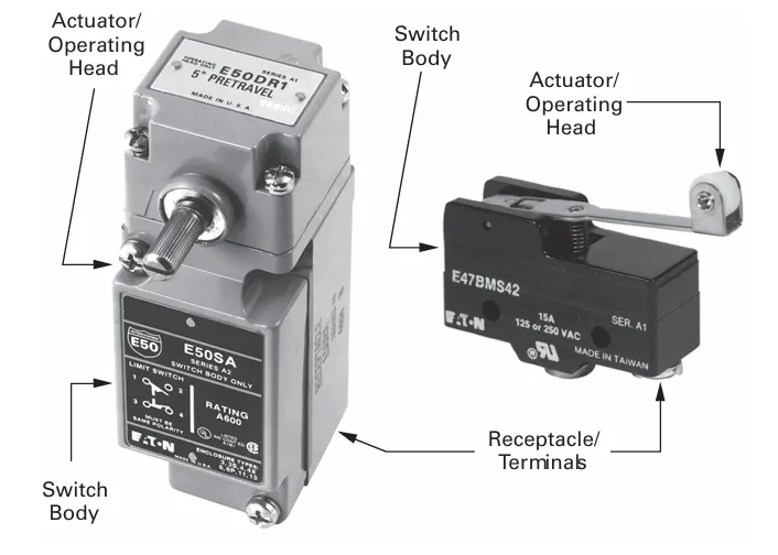
- 1. Operating Head and Actuator: This is the part of the switch that comes into contact with the moving object. It converts mechanical motion into electrical action. The head can be rotated in 90-degree increments for flexible installation, and the actuator—such as a lever with a roller—can be adjusted 360 degrees around the shaft for precise positioning.
- 2. Switch Body/ Enclosure Case: The switch body contains the core mechanism and includes a threaded conduit entry for wiring. It holds the contact block and securely attaches to the operating head, forming the main structural part of the device.
- 3. Contact Block: This part includes the electrical switch mechanism along with terminals or screw connectors for wiring. It performs the actual switching function when actuated by the internal plunger and spring system.
Which Internal Parts Are Visible in the Limit Switch Diagram?
The cross-sectional diagram of the limit switch, shown above, illustrates several important internal and external components that contribute to its function:
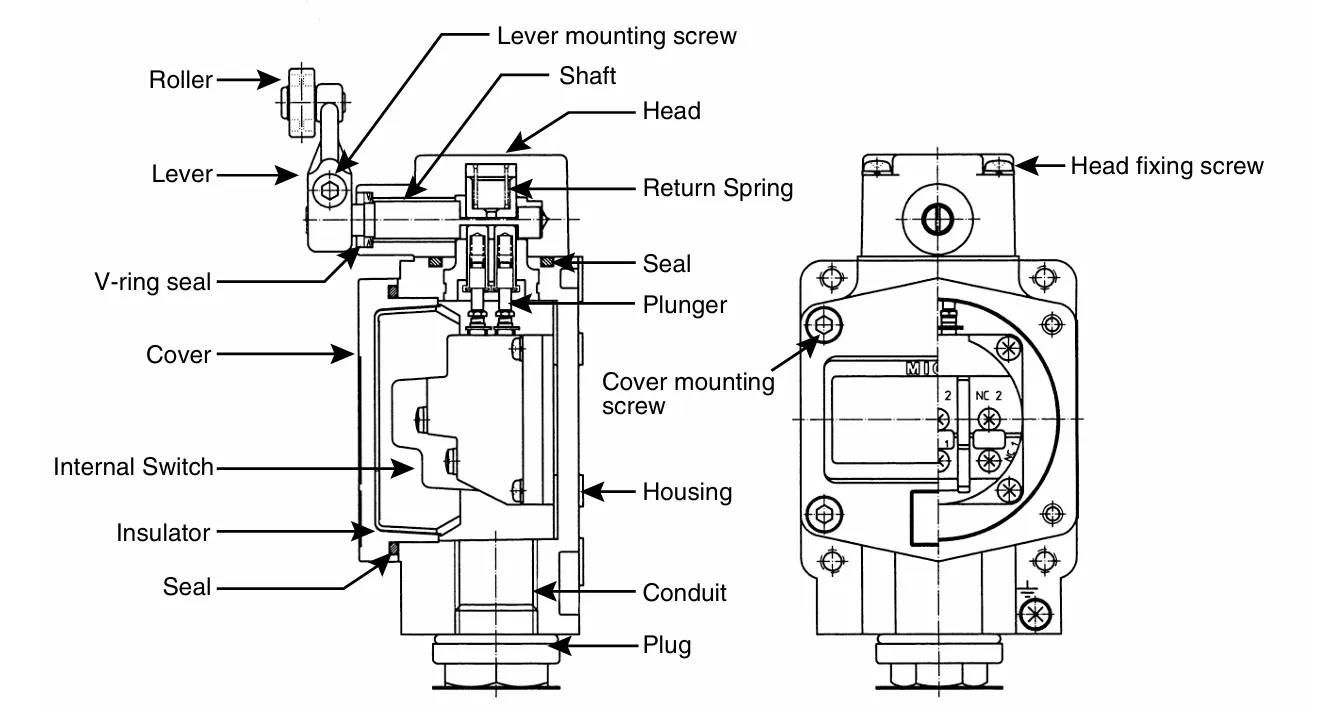
- Roller: A rotating wheel attached to the actuator lever that contacts moving objects to trigger the switch.
- Lever: A mechanical arm that transfers force from the roller to the internal plunger.
- Lever Mounting Screw: Secures the lever to the shaft, allowing firm movement and adjustment.
- Shaft: Connects the actuator mechanism to the switch body; it allows rotational or linear motion.
- Head: The top section of the switch that houses the actuator components.
- Return Spring: Brings the plunger and actuator back to their original position after activation.
- Seal: Prevents dust, oil, and moisture from entering the switch housing and damaging internal parts.
- Plunger: The internal component that moves down when the actuator is triggered, causing the contact block to operate.
- Cover: A protective plate that encloses the internal switch components.
- V-ring Seal: A circular seal designed to offer enhanced protection against contaminants like oil and water.
- Cover Mounting Screw: Fasteners used to secure the cover to the switch housing.
- Internal Switch: The main electrical switching mechanism that opens or closes the circuit.
- Insulator: An internal layer that prevents electrical short-circuiting and protects the contact block.
- Housing: The main body of the limit switch that contains and supports all internal parts.
- Conduit: An entry point or fitting where wiring is routed into the switch body for electrical connection.
- Plug: A sealed outlet or closure used to protect unused conduit entries from contamination.
- Head Fixing Screw: Screws that secure the head of the switch to the main housing, ensuring structural integrity.
Each of these elements plays a specific role. For example, the plunger and return spring help reset the actuator after it has been triggered, while the V-ring seal and housing provide mechanical strength and environmental protection. These parts work together to ensure reliable operation in industrial control systems.
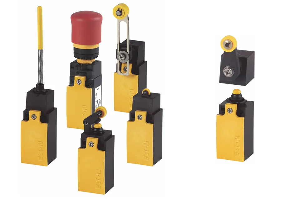
Types of Limit Switches and Their Uses
Limit switches come in a variety of types based on their construction, actuation method, and application. Each type is suited for specific industrial needs depending on motion direction, mounting requirements, and environmental conditions. Below are the most common types and where they are typically used:
-
1. Lever Type Limit Switch:
This switch features a pivoted lever arm with or without a roller. It activates when an object pushes the lever.
Use: Conveyor systems, packaging lines, elevators, and automated doors. -
2. Roller Plunger Type:
A plunger with a roller on top is pushed directly to operate the switch. It combines vertical motion sensing with rolling contact.
Use: Position sensing in automated machines, assembly lines, and robotics. -
3. Spring Rod (Whisker) Type:
Uses a flexible spring rod that bends when touched, triggering the internal switch. It is sensitive and works well with light contact.
Use: Detecting lightweight objects or delicate parts in production lines. -
4. Rotary Lever Type:
A rotating arm (sometimes spring-loaded) is deflected by an object to operate the internal switch.
Use: Multi-directional object detection in material handling and mechanical control systems. -
5. Adjustable Rod Type:
Features a long, flexible rod that can detect objects from various directions. The rod length and position can be customized.
Use: Detection of irregular or oversized items on conveyors or sorting machines. -
6. Enclosed Type (Weatherproof or Sealed):
Designed with IP-rated enclosures to resist dust, water, and chemicals.
Use: Outdoor machinery, washdown areas, oil and gas industries, and harsh environments. -
7. Precision Limit Switch:
Offers tight actuation points and minimal hysteresis, used for high-accuracy applications.
Use: CNC machines, robotics, and fine motion control systems.
Limit Switch Actuator Types and Their Selection Methods
Limit switch actuators come in various types, each with distinct operational characteristics such as pre-travel (PT), overtravel (OT), operating force (OF), repeat accuracy, and mechanical resistance to shock and vibration. Selecting the right actuator depends on the movement style, sensitivity, mounting conditions, and environmental factors. Below is a breakdown of commonly used actuator types and their applications:
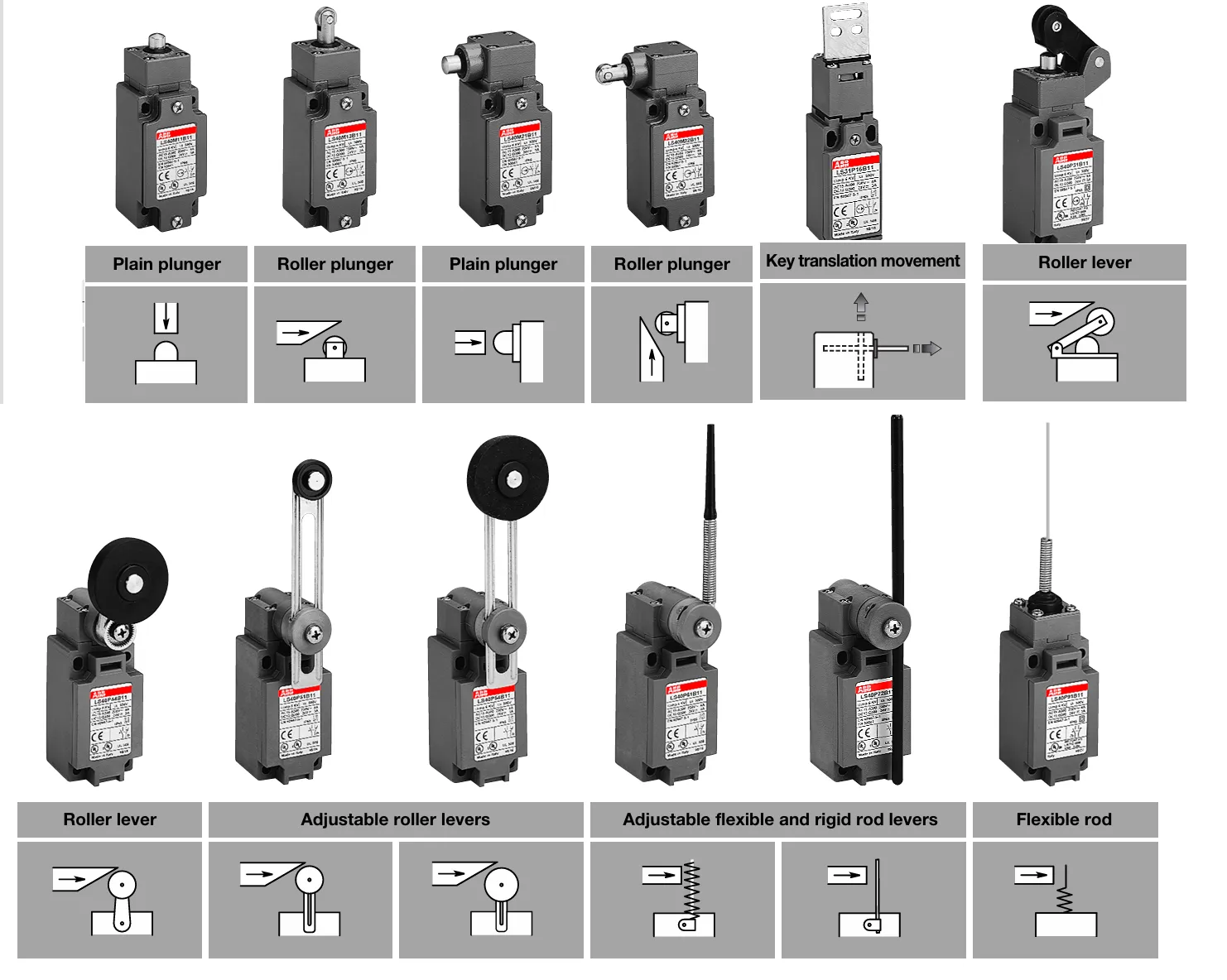
1. Roller Lever
A widely used actuator with a rotating lever and roller tip. It offers a broad actuation angle (typically 45° to 90°), adjustable direction, and is ideal for rough dog detection in object positioning. Available in models with high sensitivity and wide travel ranges.
Use: Conveyor systems, limit position detection in machines, packaging lines.
2. Adjustable Roller Lever
Similar to the roller lever, but the length of the lever is adjustable. Offers flexibility in sensing targets with varying positions or sizes. However, countermeasures may be needed to prevent lever shaking.
Use: Applications requiring mechanical flexibility such as uneven dog positions in heavy-duty systems.
3. Adjustable Rod Lever
A flexible rod-shaped actuator that is easy to bend and adjust in length. Requires very low operating force and works well for detecting wide or irregular dog surfaces. Suitable for light-contact applications.
Use: Low-force environments, irregular objects, detection of parts on sorting conveyors.
4. Fork Lever Lock Type
Features a locking mechanism that activates at 55° and locks at 90°. Ideal for bi-directional or reciprocating systems using a single or dual dog setup.
Use: Press machines, automatic feeders, or dual-point activation machinery.
5. Plunger
A linear actuator that is pressed directly. Requires accurate alignment and clean load direction to avoid damage. Provides precise point sensing.
Use: Hydraulic/pneumatic actuated systems, vertical presses, or machines requiring high positional accuracy.
6. Roller Plunger
Combines a plunger with a roller for wider actuation angle and smoother contact. Works well with cams or dogs from varying directions.
Use: Automotive lines, robot arms, cam-driven machinery.
7. Ball Plunger
A plunger with a steel ball at the tip, allowing actuation from any direction. Ideal when alignment is difficult.
Use: Detection where motion is multi-directional, such as in X-Y axis platforms.
8. Bevel Plunger
A hardened plunger with a 120° bevel edge, built for long life and abrasion resistance. Offers high repeat accuracy and minimal wear.
Use: Multi-position sensing in machining centers or high-precision CNC equipment.
9. Coil Spring Actuator
A flexible spring that can deflect in any direction except along its axis. Very low operating force required and highly adaptable to irregular or inconsistent contact.
Use: Detection of misaligned or variable-height objects, packaging lines, delicate parts handling.
10. Hinge Lever
A simple pivoting arm used with low-speed cams. Offers good adjustability and can be shaped to match specific objects.
Use: Low-speed machinery, inspection arms, and indexing tables.
11. Hinge Roller Lever
A hinge lever with a roller at the end, suitable for faster actuation. The operating speed must be controlled to remain within safe limits.
Use: Cam-driven limit switches, repetitive stamping machines.
12. Roller Arm Lever
Offers an adjustable roller position for flexible mounting. Allows for customized contact angles.
Use: Automated transfer systems, mechanical tracking, or adjustable feed equipment.
Advantages and Considerations of Limit Switches
Advantages of Limit Switches
- Proven Technology: Limit switches use well-established normally open (NO) and normally closed (NC) contact mechanisms, with a large global installation base and decades of field reliability.
- Versatile Sensing: Capable of detecting a wide variety of materials and objects through different actuator styles like levers, plungers, or rollers.
- Simple Status Detection: Switch operation is easy to detect audibly via the “click” of the snap-action mechanism or visually using a multimeter.
- Easy Troubleshooting: Diagnostic checks can be quickly performed using a digital meter or by listening for the mechanical actuation sound.
- Reliable Contact Design: Most models feature a double-break contact mechanism, enhancing switching performance and reliability under load.
- Multiple Contact Options: Select models offer up to four independent sets of contacts, allowing greater flexibility for complex control circuits.
- Positive Opening NC Contacts: Some catalog-listed models include “positive opening” normally closed contacts for safety-critical applications.
- Rugged Construction: Durable sealed housings rated to IP or NEMA standards ensure reliable operation in demanding industrial environments.
- Environmental Durability: Suitable for both indoor and outdoor use, including areas with dust, moisture, temperature variation, or vibration.
- AC/DC Compatibility: Certain models are compatible with both AC and DC power supplies, improving application flexibility.
- Power Load Switching: Capable of switching a variety of electrical loads, including power loads up to 10A at 24V DC and 120V AC. Some models are rated up to 600V AC and 300V DC.
- Low Electrical Loss: Minimal voltage drop across the switch contacts and virtually no leakage current ensures energy efficiency.
- Cost-Effective: Limit switches offer an economical solution for mechanical position sensing with high reliability.
Considerations When Using Limit Switches
- Contact Requirement: Direct physical contact between the actuator and target is required for operation.
- Mechanical Wear: Moving parts may wear out over time, especially in high-frequency or heavy-duty applications.
- Contact Lifespan: Electromechanical contacts typically have a shorter operational life compared to solid-state sensors.
- Speed Limitations: Not suitable for high-speed counting operations—recommended below 200 operations per minute.
While limit switches are effective for many applications, alternative sensing technologies may be better suited for non-contact or high-speed scenarios.
Magnetically Actuated Reed Switches
Reed switches are non-contact sensors that change the state of their internal electrical contacts when exposed to a magnetic field. These devices typically consist of two parts: the reed switch (sealed in a glass enclosure) and a separate magnetic actuator. When the magnet approaches, the contacts either close or open depending on the switch type.
Key Benefits of Reed Switches
- No Physical Contact Required: Switch actuation occurs through magnetic influence, eliminating mechanical wear and improving lifespan.
- Hermetically Sealed Contacts: Contacts are sealed in a glass capsule, providing excellent resistance to contamination and harsh environments.
Important Considerations
- Requires Magnet or Ferrous Target: Depending on the sensing configuration, a magnet or ferrous object must be present to trigger the switch.
- Alignment Sensitivity: Precise alignment between the sensor and target is crucial for consistent operation.
- Limited Load Capacity: Not ideal for switching large or inductive loads; typically used in low-current or signal-level applications.
Precautions for Handling and Mounting Limit Switches
To ensure the long-term performance and safety of a limit switch, it is important to follow specific handling, wiring, and environmental precautions. Below are the essential guidelines:
1. Protect Against Dust and Liquids
- Do not remove the cover or plug before wiring is complete. This prevents dust, water, or other contaminants from entering the internal components, which can cause malfunction or contact failure.
- Once wiring is finished, immediately reattach the cover to maintain the seal and environmental protection.
2. Initial Installation Protection
- When installing for the first time, use a dust-proof and waterproof cover or sheet to prevent materials like cement or paint from adhering to the switch. These substances can hinder lever movement and lead to failure.
3. Avoid Harmful Chemical Exposure
- Do not expose the switch to gases like H₂S, SOx, or corrosive atmospheres. These can degrade internal contacts and reduce performance.
- Avoid direct contact with solvents such as benzene, kerosene, or alcohol, which may damage the switch housing or internal insulation.
4. Mechanical Handling Safety
- Do not step on, strike, or place heavy objects on the limit switch.
- Never apply a force more than five times the rated operating force (OF) to the actuator lever. Excessive force can cause permanent deformation or failure.
5. Use of Locking Agents
- If using sealing compounds or thread-lockers on conduit entries, ensure they do not emit corrosive gases that can damage internal contacts or components.
6. Thermal Considerations
- Mount the limit switch using heat-insulating materials or shielding plates if it’s exposed to radiant or conductive heat sources. The switch must operate within its specified temperature range.
7. Vibration and Impact Isolation
- If installed in environments with continuous vibration or mechanical shock, make sure to isolate the switch with dampers or vibration absorbers to prevent internal damage.
8. Mounting Plate Requirements
- Ensure the mounting plate is made from rigid, durable material and shaped to withstand the operating force of the limit switch without bending or deformation.
- Always use washers when securing screws to prevent loosening due to mechanical vibrations.