ABB Functional Block Diagram Boolean operator Blocks - AND, OR & XOR
Published on Nov12, 2024 | Category: fbd
Share this Page:
functional block diagram is a graphical representation programming of plc. each block of FBD have different operation. logical operator or Boolean operator in functional diagram are AND, OR and XOR. these Boolean operator have two inputs or three inputs. each Boolean operator are inputs and outputs have only two state either true or false. these operator used in switch, contactor, coil, relay inputs and outputs etc. generally in abb have only three logical operator but you can also make other logical operator like NAND, NOR, Ex nor with the use of negation. these Boolean operator used in control situations requiring actions to be initiated when a certain combination of conditions is realized. all Boolean operator works same as truth table.
ABB Functional block diagram And Boolean operator
AND Boolean operator output is true when all inputs of AND Operator is true otherwise output is false. or we can say all inputs is in series with the output. any inputs is false than output is false. for example input of and operator have two push button when both push button are pressed than output is true. if a single push button is pressed than output is false. for output of Boolean operator all inputs are high or true(1). below is the example of AND Boolean operator in ABB functional block diagram.

first example is a 2 inputs and operator, inputs of and operator are two limit switch when both limit switch is operated than output is set to true. second example is a three inputs and Boolean operator where inputs are push button when all push button is closed than output is true.
ABB Functional block diagram OR Boolean Operator
OR Boolean operator output is true when one or more than one input of an or block is true. in or block are used where inputs are parallel to each other. any inputs is operated than output of or is set to true. for example if you have two limit switch as input of a or operator, when any limit switch is operated than output is true.

above is the example of or logical operator in fbd. first example of two inputs or logical operator and second example of three inputs or logical operator. each logical operator have bool data type. output of both or blocks are true when more than one inputs is true. output is false only when all inputs is false.
abb functional block digram XOR Boolean operator
abb functional block diagram xor Boolean operator output is true when one if the input is true, output is false when both input is true or both inputs is false. Sometimes there is a need for a gate that gives an output when either of the inputs is true but not when both are true.

above is the example of 2 inputs xor logical operator as we know output is true when any one inputs is true if all inputs is true than output is false. in this example we used two mechanical switch to on and off lamp. when any switch is on than lamp is on but if both switched is on than lamp set to off. lamp on if a single switched is pressed only.
abb functional block diagram NAND, NOR, XNOR logical gate
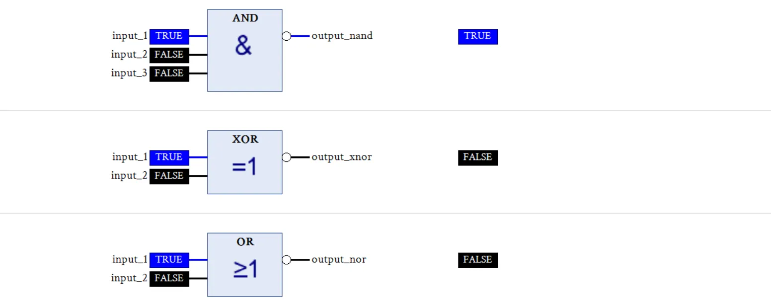
negation invert the input or output state.so for developing NAND, XNOR and NOR gate we generally placed negation in Boolean operator output. for example if we placed negation in output of an AND gate than this gate operation is same as NAND gate.

above is the example of NAND, NOR and Xnor logical gate in functional block diagram each block output used negation to invert output of Boolean gate. first example is a 3 inputs NAND gate with the use of AND Gate. second example is XNOR gate with the use of two inputs XOR gate. third example of 2 inputs NOR gate with the help of O gate.
multiple Boolean operator in functional block digram
functional block diagram allowed to use multiple blocks in same network here we make a xor logical gate with the help of NAND gate. as we know when negation is used as output of any gate than gate output is invert so in this example we have two inputs for xor gate.XOR_1_ is final output of network. output out_1_ is used for last NAND gate inputs.
