ABB Functional Block Diagrams for Industrial Automation and Control
Published on Nov08, 2024 | Category: fbd
Share this Page:
functional block diagrams is a programming language for a plc. many PLC support functional block diagrams like Siemens, ABB, ABB etc. this language used block instead of instruction like ladder. function block diagram have many features like other plc programming language. each block of FBD have different operation. in abb you can also make a program for plc functional block diagram by using automation builder software. functional block diagram have standard function like logical function, timer & counter function, comparison function block, arithmetical functional block. or you can also define your function block. abb support IEC-61131-3 standrd for FBD.
what is functional block diagram
functional block diagram is graphically blocks based plc programming language. functional block diagram have graphical block like logical blocks, timer and counter block, arithmetic and comparison blocks. FBD is short form of functional block diagram. functional block diagram easy to understand and easy to program. It works with a list of networks whereby each network contains a structure which represents either a logical or arithmetic expression. below is the example of functional block diagram networks.

how to make Functional block diagram program in abb
abb automation builder support function block diagram. basically primary programming language of abb automation builder is structured text(ST) .you can add new POU and select functional block diagram as programming language. to add POU right click on application and select add object and a dialogue open in this dialogue in category select IEC61131-3 and select POU enter the name of POU and select functional block diagram as programming language from drop down.

declare functional block diagram POU in main programming file
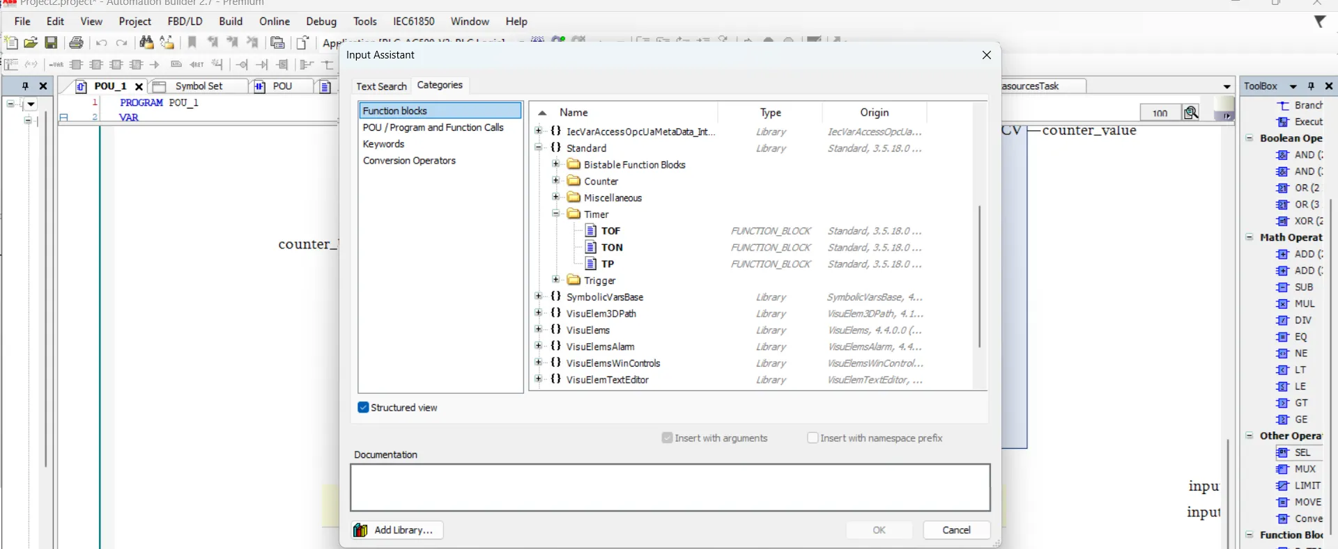
if you not add your functional block diagram POU to main program than your FBD POU not work. PLC_PRG is main programming file which are used structured text as programing language so add here your POU as function. so open PLC_PRG from task and right click and select input assistant a dialogue open in dialogue select POU/programs and functional blocks and select POU file name and press ok. after adding file now your file works.

simple program in functional block diagram
we make very simple program in functional block diagram with an and Boolean operator and a on delay timer block. below is the example of functional block diagram in abb automation builder. add a and logical block in network and than declare inputs and outputs of and blocks, in second rung add a on delay timer block and declare input, output and instance name of on delay timer block.in third rung add a 3 input addition instruction and declare all inputs and output.

what is blocks in functional block diagram
blocks are graphically representation of instruction for example and block is a block for and logical operation each blocks are used for specific operation. each blocks have inputs and outputs. blocks performs operation on these inputs and return result in output.
how to insert bloks in functional block diagram
you can add blocks in network. you can insert single or multiple block in a network. to add blocks in network press ctrl+B a input assistant dialogue open here you select your blocks.

or you can also insert blocks by drag and drop from toolbox. in toolbox select blocks and insert to selected network.

how to add multiple block in same network in functional block diagram
you can add multiple block in same network as shown below by assigning input and output of blocks. in below example we first add or block and declare both input of or block than add a on delay timer as output of or block.

simulation of functional block diagram in abb automation builder
simulation is virtual controller for your plc. simulation support all programming language it also support functional block diagram. first make your program in functional block diagram than add your pou to main program file and then build your to check program error if you have any error during program build than check and remove error and again use build option. if you don't have error than start simulation or download program to plc is possible.
