Connected Components Workbench Micro800 Counter Instructions
Published on Mar08, 2023 | Category: basicShare this Page:
Counter instructions use to control operations based on the number of events. Counter counts input bit of counter and increment or decrement by 1 when input bit of counter change. A Counter input bit is Pulses Or Events. Increment counter is known as Count up and decrement counter known as count down . counter output Depends On Type Of Counter. Counter output is total count of An Events Of How Many Times Has Occurred. when input bit of counter is change from true to false or false to true than counter start count and increment or decrement preset value by 1 every change of input bit counter. Connected Components Workbench Micro800 plc have three type of counter.
micro 800 CTU instruction
micro 800 CTU instruction increment by 1 upto preset value (maximum value of counter) of counter at change of every counter input . CTU have following parameter
- Counter UP input (C U)Input bit of counter which have bool data type. counter increment by 1 of each rising edge of counter input.falling edge of counter input (CU) hold counter value.
- Reset Input : reset counter CV value or counter data type bool.when reset set to true counter reset and no increment in counter value.
- Preset Value (P V) INPUTmaximum value or preset value of counter which has data type DINT.
- Output Q counter output data type bool. output is set to true when Counter value is greater than or equal to the maximum value (PV).
- current counter value (CV) outputit's current value output which have data type DINT. CV = CV + 1.
above is the example of micro 800 CTU instruction. the preset value (PV) is declare to 10 when at the rising edge of counter input(_IO_EM_DI_01) counter current value(CV) increment by 1, at falling edge of counter input counter hold current counter value (CV). at every rising edge of counter input, counter current value incrmented by 1 (CV = CV + 1) upto Maximum Value of counter(PV). when CV is greater than or equal to PV than counter done bit is set to true.if counter done bit is set to true and if counter input is change false to true than no increment in CV.
micro 800 CTD instruction
micro 800 CTD instruction decrement by 1 upto zero at every change of counter input if Counter PV = CV and Load input bit is set to false. if PV ≠ CV than no decrement in CV because CV is already set to zero and counter done bit is true. CTD have following parameter
- Counter Down input (C D)Input bit of counter which have bool data type. counter decrement by 1 of each rising edge of counter input. Falling edge of counter input (CD) hold counter value.
- LOAD Input : when is set to true than value of PV move to CV.if load input is set to true and CD bit change to true so no decrment in counter value so after move of PV value set Load input to false.
- Preset Value (P V) INPUTprogrammed maximum value or preset value of counter which has data type DINT.
- Output Q counter output data type bool. output is set to true when Counter value is less than or equal to the maximum value (PV).
- current counter value (CV) outputit's current value output which have data type DINT.
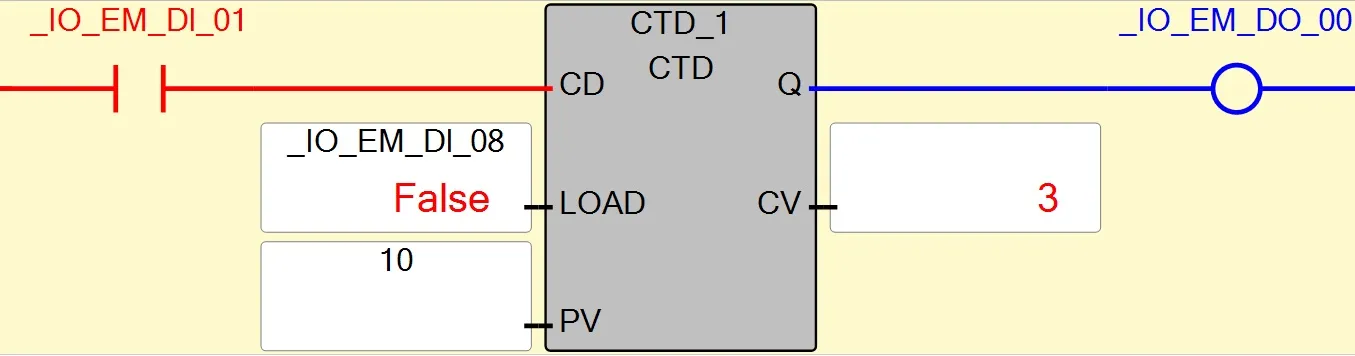
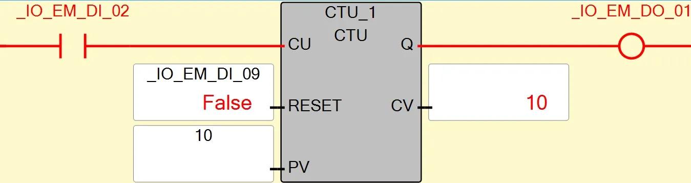
above is the example of micro 800 CTD instruction. the preset value (PV) is declare to 10 when at the rising edge of counter input(_IO_EM_DI_02) counter current value(CV) decrement by 1, at falling edge of counter input counter hold current counter value (CV). at every rising edge of counter input, counter current value decrement by 1 (CV = PV - 1) upto zero. when CV is less than or equal to Zero counter done bit is set to true.
micro 800 CTUD instruction
micro 800 CTUD instruction is count up or down. it's a combination of CTU and CTD.both operations at same time is not possible. Either you use this instruction as up counter or down counter. selection of up and down depends on counter selection bit i.e.CU or CD bit. CTUD have following parameter
- Counter UP input (C U)Input bit of counter which have bool data type. counter increment by 1 of each rising edge of counter input.
- Counter Down input (C D)Input bit of counter which have bool data type. counter decrement by 1 of each rising edge of counter input.
- Reset Input : reset counter CV value or counter data type bool.when reset set to true counter reset and no increment in counter value.
- LOAD Input : when is set to true than value of PV move to CV
- Preset Value (P V) INPUTmaximum value or preset value of counter which has data type DINT.
- Output Q U counter output of overflow data type bool. output is set to true when Counter value is greater than or equal to the maximum value (PV).
- Output Q D counter output of underflow data type bool. output is set to true when Counter value is less than or equal to the zero.
- current counter value (CV) outputstore resulted value of counter. current value output which have data type DINT.
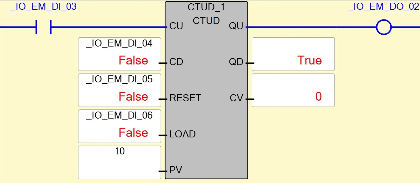
above is the example of CTUD instruction at rising edge of counter up (CU) bit CTUD operations same as CTU and rising edge of CD bi CTUD operation same as CTD. for counter up operation make sure CU have rising edge, reset and load bit set to false, and for counter down operation make sure CV = PV and reset and load bit is set to false. when CV is greater than or equal to zero than counter overflow bit is set to true. And if Counter value is less than or equal to the zero than underflow bit (QD) set to true.