Differential Pressure Transmitters: Principle, Types, and Uses
Published on July 18, 2024 | Category: introductionShare this Page:
Differential pressure transmitters are vital tools in modern process automation and control systems. Unlike standard transmitters, they measure the pressure difference between two points in a system—providing essential data for accurate flow monitoring, level detection, filter performance, and more. This guide offers a complete overview of how differential pressure transmitters work, including their internal sensing technologies such as capacitive, strain gauge, piezoresistive, and resonant wire methods.
You'll learn about the components inside the transmitter, output signal standards (like 4–20 mA, HART, and Fieldbus), and best practices for installation—covering impulse tubing, mounting orientation, and manifold usage. We also walk you through step-by-step calibration methods for zero and span, and address typical troubleshooting issues such as impulse line blockage, electrical noise, and signal deviation.
Whether you're an instrumentation engineer, plant technician, or preparing for a technical interview, this page offers real-world examples, diagrams, and clear explanations to help you understand, install, and maintain differential pressure transmitters effectively.Additionally, we compare differential, gauge, and absolute pressure types to help you select the right sensor for your application.
Differential Pressure and Differential Pressure Transmitter Guide
What is Differential Pressure?
Differential pressure (ΔP) is the difference in pressure between two points in a system. It is calculated as:
ΔP = P1 - P2
Where P1 is the pressure at point A, and P2 is the pressure at point B. Unlike gauge or absolute pressure, differential pressure focuses on the relative difference within a system. It is widely used in flow, filter condition, and level measurement in closed tanks.
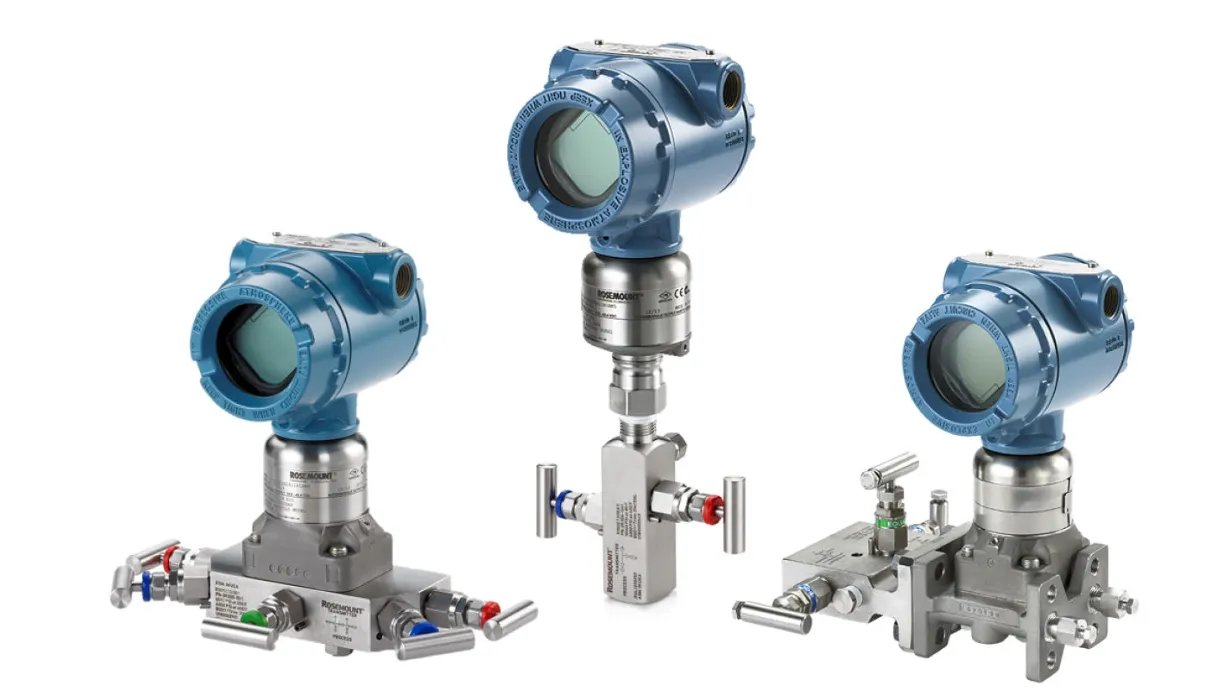
What is a Differential Pressure Transmitter?
A differential pressure transmitter measures the difference between two pressure points. It has two ports: one connected to the high-pressure side (HP), and the other to the low-pressure side (LP). The transmitter converts this difference into an electrical signal, typically 4–20 mA or a digital output like HART or Foundation Fieldbus.
DP transmitters are essential in applications such as fluid level detection, flow monitoring, and filter health checking in industrial systems.
Types of Differential Pressure Transmitters
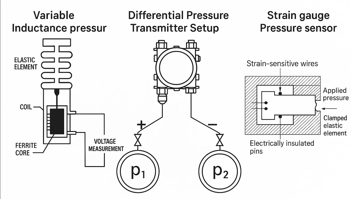
Based on their sensing principle, DP transmitters are categorized into:
- Strain Gauge: Uses diaphragm deflection to change strain gauge resistance.
- Capacitive: Diaphragm changes capacitance between electrodes.
- Inductive: Ferromagnetic core changes inductance with pressure difference.
- Piezoresistive: Silicon elements change resistance under stress.
- Resonant Wire: Pressure shifts frequency of vibrating wire.
- MEMS/Optical: Modern microelectromechanical or fiber-optic sensors for harsh environments.
Working Principle of Differential Pressure Transmitter
A flexible diaphragm separates the high and low-pressure sides. Pressure causes diaphragm deflection, which is detected by a sensing element (e.g., strain gauge, capacitive plate, or piezoresistive sensor).
This deflection is converted into an electrical signal and output as a 4–20 mA or digital signal. It is used for accurate control and monitoring of process variables.
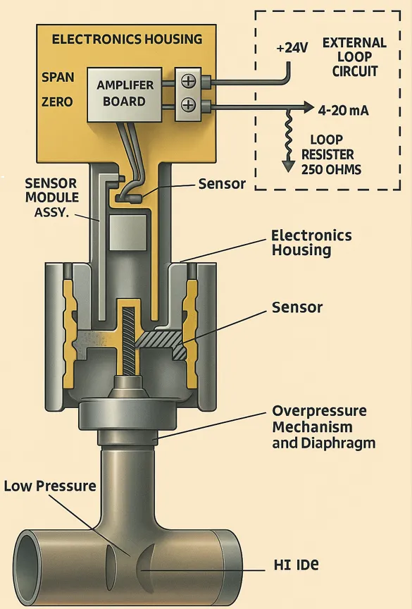
Internal Construction and Working
Inside a metallic measuring cell, process media apply pressure to isolating diaphragms filled with transmission oil. This pressure is transmitted to a piezoresistive sensor, forming a Wheatstone bridge. The resulting voltage change is amplified, digitized, and processed.
Onboard electronics compensate for temperature and static pressure. Overpressure protection safeguards the sensor.
Main Components of a Differential Pressure Transmitter
- Electronics Housing: Holds amplifier and adjustment modules.
- Amplifier Board: Converts sensor signal into output signal.
- Sensor Module: Core pressure-sensing unit.
- Flanges (HI/LO): Connection points to process lines.
- Isolation Diaphragm: Protects sensor, transmits pressure via fill fluid.
- Overpressure Diaphragm: Prevents damage during pressure spikes.
High/Low Side Port Identification
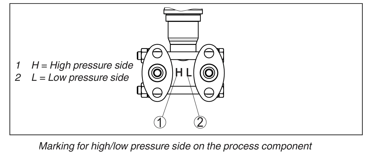
Always connect the "H" port to the higher pressure source and "L" port to the lower. Incorrect connections may produce reverse (negative) readings, affecting interpretation or control.
DP Transmitter System Components
Key Elements
- Primary Element: Creates pressure drop (e.g., orifice plate).
- Secondary Element: Sensor module to detect pressure difference.
- Electronics Housing: Converts the sensed signal to 4–20 mA or digital signal.
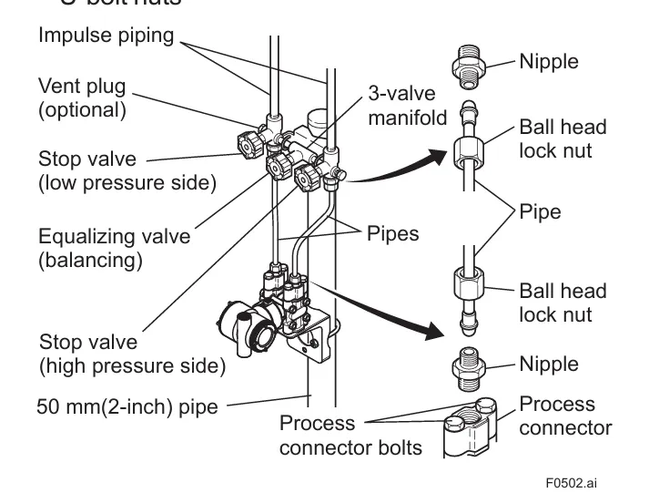
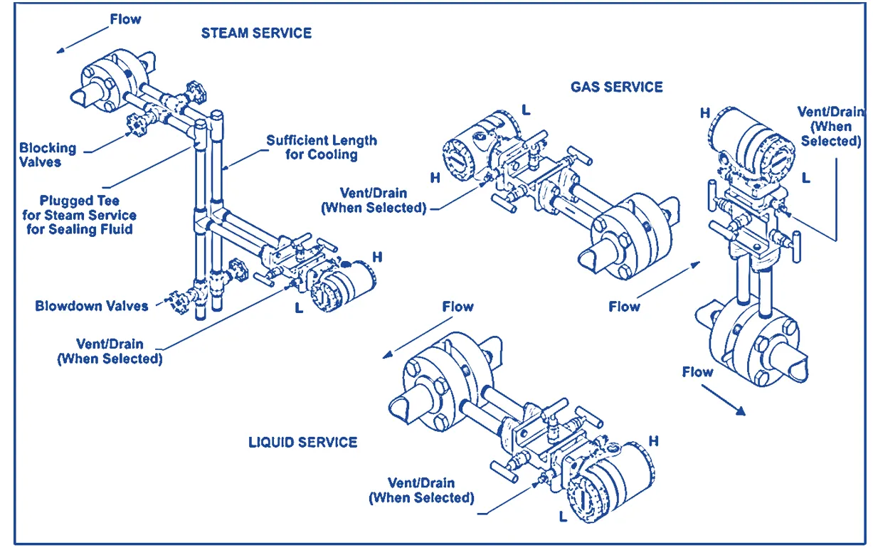
Instrumentation Manifolds for DP Transmitters
What is a Manifold?
A manifold is a valve assembly that isolates, equalizes, and vents pressure instruments during installation, maintenance, or calibration. It is mounted between the process line and the transmitter.
Types of Manifolds
- 2-Valve Manifold: For pressure transmitters. Includes one block and one vent valve.
- 3-Valve Manifold: For DP transmitters. Two block valves (HI & LO) and one equalizing valve.
- 5-Valve Manifold: Advanced version with additional vent/drain valves.
Valve Functions
Equalizing Valve
Balances pressure before startup or calibration, protecting the sensor from sudden pressure differences.
Drain/Vent Valve
Releases trapped pressure or process fluid before transmitter removal or calibration.
Block Valve
Isolates the transmitter from the process, allowing safe maintenance or replacement.
Calibration and Troubleshooting
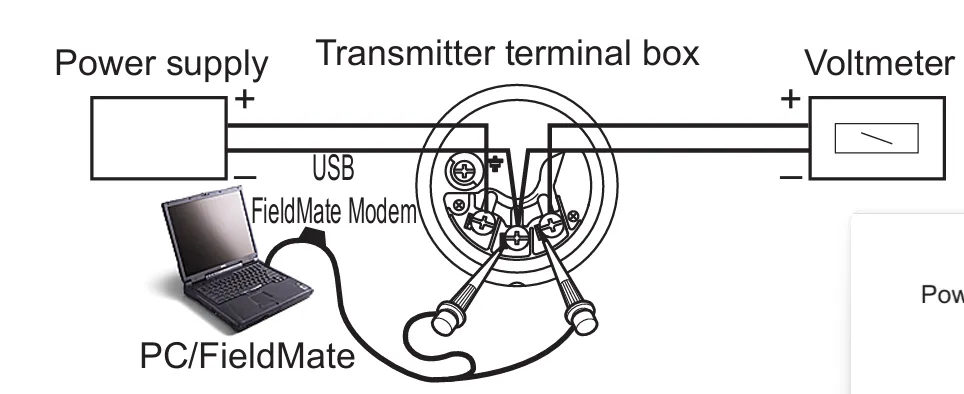
How to Calibrate a Differential Pressure Transmitter
- Isolate the transmitter using the manifold.
- Connect a pressure calibrator to HP and LP ports.
- Apply known pressure steps (0–100%).
- Compare output with expected values (e.g., 4–20 mA).
- Adjust zero/span settings as needed.
Troubleshooting Common Issues
- No Output: Check 24V supply, wiring, and loop continuity.
- Incorrect Reading: Check for blockages or leaks in impulse lines.
- Fluctuating Output: Address vibration, air in lines, or unstable processes.
- Zero/Span Shift: Perform trimming or recalibration.
- Valve Positioning: Ensure equalizing and block valves are correctly set.
- Manifold Leakage: Tighten fittings and inspect gaskets.
Applications of Differential Pressure Transmitters
1. Pressure Measurement
Measures line or system pressure in gases, vapors, or liquids—both corrosive and non-corrosive.
2. Differential Pressure Monitoring
- Detects pressure drop across filters or flow elements.
- Ranges: 20 mbar to 30 bar (0.29 to 435 psi).
3. Level Measurement
- Open tanks: LP port vented to atmosphere.
- Closed tanks: Both ports connected to vessel.
- Typical range: 250 mbar to 5 bar.
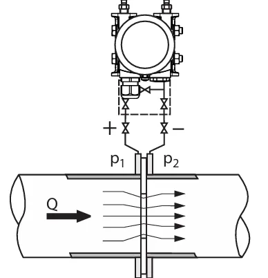
4. Flow Measurement
- Volume Flow: Uses pressure drop across orifice or venturi.
- Mass Flow: Incorporates temperature/pressure compensation.
5. Absolute Pressure
Some models measure absolute pressure with high overload capabilities:
- Pressure range: 250 mbar to 30 bar
- DP range: 250 mbar to 100 bar
Note: Always refer to the manufacturer’s datasheet for correct range selection, chemical compatibility, and safety certifications.
Communication Methods in Differential Pressure Transmitters
Overview of Communication in DP Transmitters
Differential Pressure (DP) transmitters convert the measured pressure difference into a signal that can be transmitted to a control system such as a PLC, DCS, or SCADA. These signals can be either analog or digital depending on the type of communication used.
Choosing the right communication method affects signal quality, diagnostics, data integration, and system compatibility.
1. 4–20 mA Analog Signal
This is the most common and widely used communication method in industrial automation. The pressure difference is converted into a current signal ranging from 4 mA (minimum value) to 20 mA (maximum value).
- Simple and robust — immune to electrical noise over long distances.
- Loop-powered — transmitter can be powered using the same 2 wires that carry the signal.
- Used in: Basic control systems and legacy systems where only one process variable is needed.
2. HART Protocol (Highway Addressable Remote Transducer)
HART is a hybrid communication protocol that allows digital communication over the same 4–20 mA analog wires. It enables access to additional device information without disrupting the primary analog signal.
- Analog + digital: 4–20 mA signal used for control; digital signal for diagnostics/configuration.
- Smart features: Device diagnostics, sensor status, tag numbers, and calibration settings can be accessed remotely.
- Tools: Requires a HART communicator or HART-enabled software.
- Ideal for: Applications needing remote configuration or maintenance.
3. Foundation Fieldbus
Foundation Fieldbus is a purely digital, two-way communication protocol. It allows multiple devices to connect on a single cable segment and share process data.
- All-digital communication: No analog signal used.
- Multivariable data: Transmit several process variables (e.g., pressure, temperature) and diagnostics.
- Peer-to-peer and control-in-the-field capabilities — advanced control logic can be executed in the transmitter itself.
- Used in: Complex or distributed control systems in large-scale automation projects.
4. Profibus PA (Process Automation)
Profibus PA is a digital protocol designed for process industries. It uses the same physical layer as Foundation Fieldbus but follows a different communication standard.
- Multidrop: Supports multiple instruments on a single cable.
- High data integrity: Reliable for critical and safety applications.
- Integration: Common in European and Siemens-based control systems.
Comparison Table of DP Transmitter Communication Methods
| Protocol | Signal Type | Key Features | Use Case |
|---|---|---|---|
| 4–20 mA | Analog | Simple, loop-powered, noise-immune | Basic monitoring and control |
| HART | Analog + Digital | Diagnostics, remote configuration | Smart transmitters with basic control |
| Foundation Fieldbus | Digital | Multivariable, advanced diagnostics | Large DCS installations |
| Profibus PA | Digital | High-speed, multi-instrument, control-ready | European process industries |
Conclusion
Selecting the right communication method for a differential pressure transmitter depends on system complexity, required diagnostics, compatibility with control systems, and the level of automation. While 4–20 mA with HART remains the most common, digital protocols like Foundation Fieldbus and Profibus PA offer powerful features for modern smart plants.
tadiwachiwawarirwa
April 22, 2026, 2:34 pmsplendid indeed now I fully understand