Pressure Transmitter – Working Principle, Types, Applications, Installation & Calibration
Published on July 18, 2024 | Category: introductionShare this Page:
A pressure transmitter like the ABB 2600T,rosemount Cerabar S PMC71 etc. series is used to measure various forms of pressure, including gauge pressure (barg, psig), absolute pressure (bara, psia), and vacuum pressure (inches or cm H₂O). It works by converting pressure measurements into standardized electrical signals such as 4–20 mA, 0–5V/10V, or RS485 digital outputs, which can be transmitted to controllers, PLCs, or monitoring systems.
This page offers a comprehensive guide to Pressure Transmitters in process instrumentation, covering working principles, types (gauge, absolute, differential), sensor technologies (piezoresistive, capacitive, strain gauge), and signal conversion. It also includes installation methods, calibration procedures, wiring diagrams, industrial applications, and troubleshooting tips. Ideal for interview preparation or field reference, this resource is suitable for both beginners and experienced engineers in the instrumentation field.
What is Pressure? Definition and Types
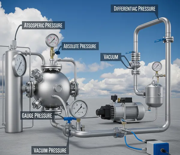
Pressure is defined as the force applied per unit area. It is a fundamental physical quantity used to describe the intensity of force exerted by a fluid (liquid or gas) on a surface. In industrial instrumentation, understanding different types of pressure is essential for selecting the correct transmitter or sensor for process control and measurement.
- Atmospheric Pressure: The pressure exerted by the Earth's atmosphere at sea level, typically around 14.7 psi (101.3 kPa).
- Barometric Pressure: A form of atmospheric pressure measured with a barometer; commonly used in meteorology.
- Hydrostatic Pressure: The pressure created by a liquid in a column due to gravity, often used in level measurement.
- Line Pressure: The pressure of fluid flowing through a pipeline, acting along the walls of the pipe.
- Static Pressure: The pressure in a system when the fluid is at rest; same as line pressure in many cases.
- Working Pressure: The normal operating pressure in a system; generally equals the static pressure under standard conditions.
- Absolute Pressure: The total pressure measured relative to a perfect vacuum (0 psia).
- Gauge Pressure: The pressure measured relative to atmospheric pressure (0 psig = atmospheric pressure).
- Vacuum Pressure: Pressure lower than atmospheric pressure, usually expressed in inches or centimeters of H₂O below ambient pressure.
What is a Pressure Transmitter?
A pressure transmitter is an instrument that converts the physical force of pressure into a standardized electrical signal—typically a 4–20 mA current loop. This signal can be easily transmitted to and interpreted by controllers, PLCs, or DCS systems for monitoring and control purposes.
Also known as a pressure transducer, this device measures the expansive force of a liquid or gas sample. It consists of a pressure-sensitive surface—commonly made of stainless steel, silicon, or ceramic—depending on the process medium. When pressure is applied to this surface, internal electronics convert the mechanical force into an electrical output signal.
Pressure transmitters are widely used in industrial automation, process control, hydraulics, and fluid systems to ensure accurate and reliable pressure measurement.
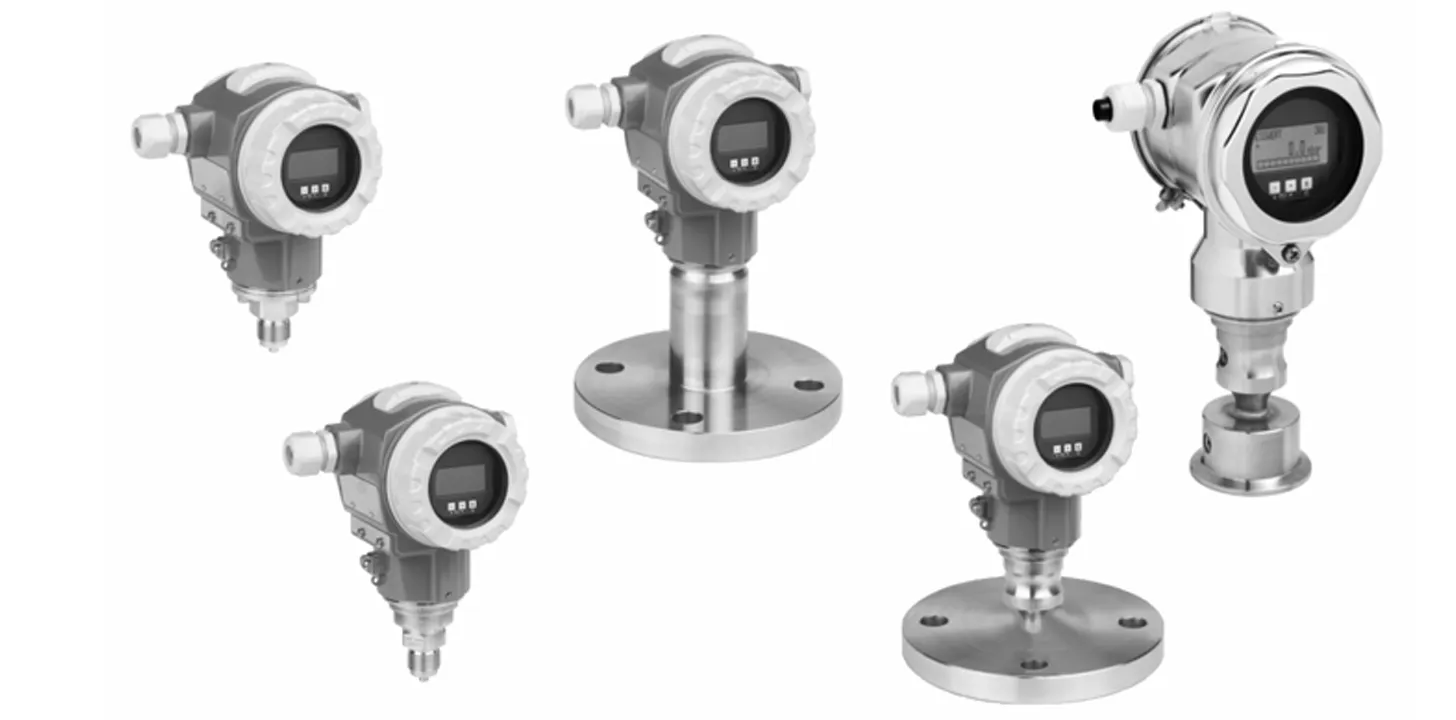
types of pressure tranmitterTypes of Pressure Transmitters
Pressure transmitters are categorized based on how they reference and measure pressure. Each type serves a specific application in industrial or process environments. Below are the most common types of pressure transmitters:
- Gauge Pressure Transmitter (PG): Measures pressure relative to atmospheric pressure. Commonly used in tanks, pipes, and open systems.
- Absolute Pressure Transmitter (PA): Measures pressure relative to a perfect vacuum (zero reference point). Useful in high-accuracy applications like vacuum systems or altitude measurements.
- Differential Pressure Transmitter (DP): Measures the difference between two pressure points. Widely used in flow measurement (with orifice plates, venturi tubes), level sensing, and filter monitoring.
- Sealed Gauge Pressure Transmitter: Similar to gauge type but sealed against atmospheric conditions, used in harsh or changing environments.
- Multivariable Pressure Transmitter: Measures multiple parameters—typically differential pressure, static pressure, and temperature—to calculate flow and energy in complex systems.
Working Principle of a Pressure Transmitter
A pressure transmitter works by converting applied process pressure into an electrical signal using a combination of mechanical and electronic components. The core principle it operates on is Pascal’s Law, which states that pressure applied to a confined fluid is transmitted equally in all directions.
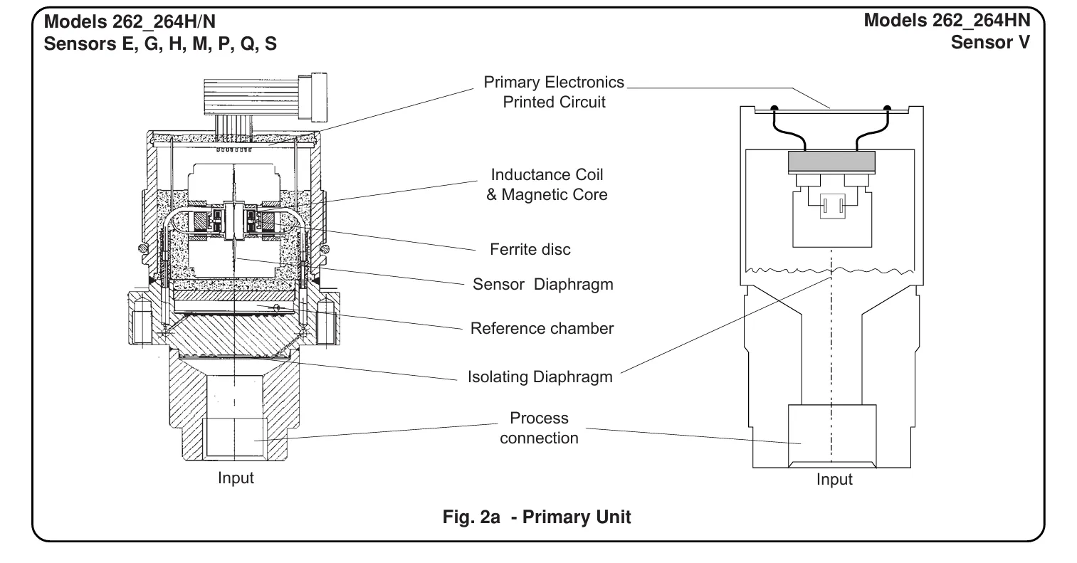
- Pressure Sensing: The process pressure is applied to an isolation diaphragm that separates the process fluid from the internal components of the transmitter.
- Fill Fluid Transmission: The pressure is transferred through an incompressible fill fluid inside the sensor assembly, maintaining the same pressure as the process side.
- Sensor Output: This pressure is detected by a built-in sensor, which converts it into a small electrical signal (usually millivolts).
- Signal Conditioning: The internal electronics amplify and condition the signal, compensating for factors like ambient temperature, vibration, or electrical noise.
- Standardized Output: Finally, the conditioned signal is converted into a standard output, typically a 4–20 mA current signal, suitable for use in control systems like PLCs, DCS, or SCADA.
- Protection and Housing: The entire assembly is enclosed in a weatherproof housing, ensuring durability and protection from harsh industrial environments.
Working of a Pressure Transmitter
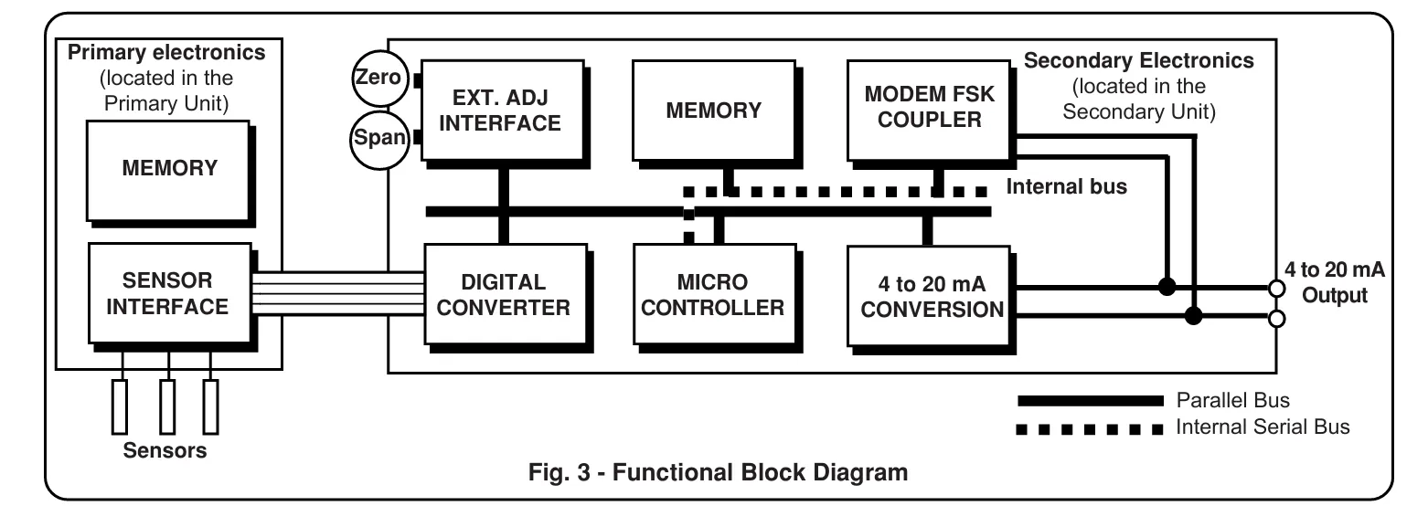
A pressure transmitter operates by sensing pressure and converting it into an electrical signal that can be read and processed by control systems like PLCs, DCS, or display units. The working principle involves three main stages: sensing, signal conversion, and transmission.
- 1. Pressure Sensing: The process fluid applies force to a pressure-sensitive element (such as a diaphragm) inside the transmitter. This element deforms proportionally to the applied pressure.
- 2. Signal Conversion: The deformation is detected by a sensor (e.g., strain gauge, piezoresistive, or capacitive sensor) which converts the mechanical displacement into a small electrical signal (usually in millivolts).
- 3. Signal Conditioning and Transmission: The weak signal is amplified, linearized, and converted into a standardized output—most commonly a 4–20 mA current loop, 0–10 V signal, or digital output like HART or RS485. This output represents the measured pressure and is sent to the control system for monitoring or further action.
Some advanced pressure transmitters also include temperature compensation, digital displays, diagnostics, and communication protocols to ensure high accuracy and reliability under varying process conditions.
Measuring Principles of Pressure Transmitters
Modern pressure transmitters use several sensing technologies to convert pressure into an electrical signal. Below are the six most commonly used and important sensing methods:
-
1. Electromechanical Strain Gauge
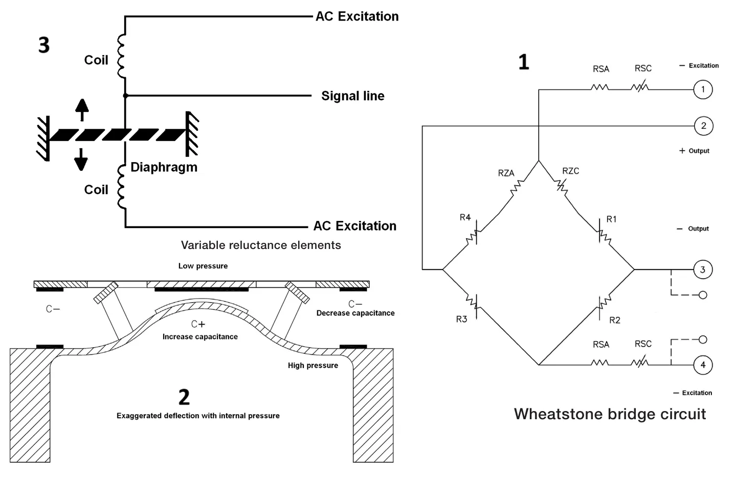
Strain gauges are bonded to a diaphragm and connected in a Wheatstone bridge. Pressure causes tiny deformations, changing resistance and producing a voltage. It's widely used, but sensitive to temperature.
-
2. Variable Capacitance
A diaphragm moves with pressure, changing the capacitance between it and a reference plate. This variation is converted to an electrical output. Common in low-pressure, high-accuracy applications.
-
3. Variable Reluctance
Pressure deflects a diaphragm placed between coils, altering the magnetic flux and coil inductance. This change generates a signal that corresponds to the applied pressure. Known for high sensitivity to small changes.
-
4. Piezoresistive
Based on semiconductor materials that change resistance when strained by pressure. Offers high sensitivity and compact design, suitable for harsh or dynamic environments.
-
5. Resonant Wire
A wire is tensioned by a diaphragm and vibrates at a natural frequency. As pressure changes, the tension and frequency shift. This frequency is measured electronically. It provides excellent long-term stability and low drift.
-
6. Optical Sensing
Uses light-based methods to detect diaphragm movement. Pressure-induced deflections alter the light path or intensity, which is measured by photodetectors. It offers immunity to EMI and is ideal for hazardous or high-voltage environments.
Each sensing technique has unique advantages. The choice depends on required accuracy, environmental factors, signal stability, and cost.
Signal Transmission Methods in Pressure Transmitters
Pressure transmitters use various signal transmission techniques to send process pressure data to controllers and monitoring systems. These methods ensure accurate and reliable communication, even over long distances.
- Four-Wire Transmission: Two wires provide power and two carry the signal. Common in remote areas with alternate power sources such as batteries or solar panels.
- Two-Wire Transmission: Uses a 4–20 mA loop where both power and signal share the same two wires. Ideal for standard industrial setups with minimal wiring.
- Smart Transmission: Digital signals are superimposed on the analog loop (HART protocol), enabling advanced diagnostics and remote configuration.
-
Fieldbus Transmission: A digital, multi-drop system that allows multiple field devices to communicate over the same two wires. Efficient for modern automation systems.
Installation of a Pressure Transmitter
Proper installation of a pressure transmitter is crucial to ensure accurate readings and long-term reliability. It involves correct positioning, clean mounting surfaces, and proper connection to the process and electrical systems.
- Select Proper Location: Choose a vibration-free, accessible location, ideally close to the tapping point but above the process line to avoid fluid ingress.
- Mounting Orientation: Mount vertically for liquid service and horizontally (diaphragm facing down) for gas service. Orientation affects pressure head and must be considered for accurate measurement.
- Use Isolation Valves: Install manifold valves between the process and transmitter to allow easy calibration, venting, and isolation during maintenance.
- Avoid Pulsations: For pulsating services (e.g., pumps), install a snubber or dampener to protect the sensor from damage.
- Use Proper Impulse Lines: Use short and equal-length impulse lines for differential pressure transmitters to avoid pressure drop errors.
- Seal and Tighten Connections: Ensure leak-proof connections using proper sealing materials like PTFE tape and avoid over-tightening.
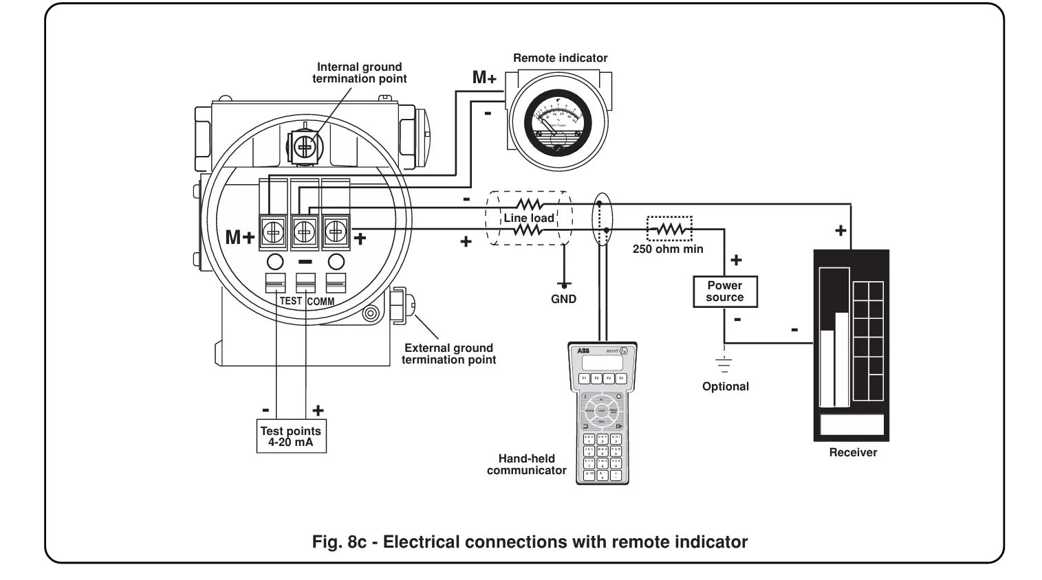
- Wiring: Use shielded cables for signal transmission. Route cables away from high-voltage lines to avoid interference.
- Grounding: Always ground the transmitter as per the manufacturer's recommendations to avoid electrical noise and ensure safety.
Installation Guidelines of Pressure Transmitters for Different Media
Installing pressure transmitters varies depending on the type of process media. Each media—such as gas, dust, oil, or liquid—has specific installation requirements to ensure safe and accurate measurement. Below are the recommended practices based on the medium:
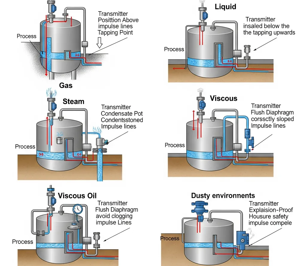
- For Gas Measurement: Mount the pressure transmitter above the tapping point. Ensure the impulse line slopes downward toward the process to prevent gas accumulation. Use condensation traps if necessary to avoid moisture entry.
- For Liquid Measurement: Mount the transmitter below the tapping point to ensure the sensor stays filled with fluid. Avoid air pockets and ensure vertical mounting for stable pressure head.
- For Steam or High-Temperature Fluids: Use a condensate pot or steam impulse piping to protect the transmitter from heat damage. Always install above the tapping point with equal-length impulse lines for differential pressure types.
- For Viscous Fluids or Oils: Install flush diaphragm-type transmitters to prevent clogging. Use heating jackets or keep the transmitter close to the process to reduce viscosity changes due to temperature.
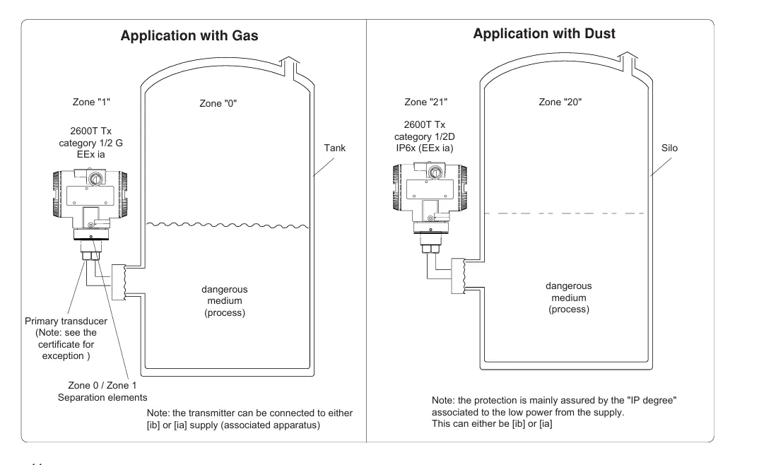
- For Dusty Environments: Choose a dust-tight or explosion-proof enclosure. Use proper filtering at the tapping point to prevent clogging of impulse lines or ports. Ensure transmitter is sealed and mounted away from direct dust streams.
- For Corrosive Media: Use chemically compatible wetted parts such as PTFE lining or Hastelloy diaphragms. Mount in a way that allows flushing and maintenance access.
Calibration Methods of Smart Pressure Transmitters
Smart pressure transmitters use microprocessor-based technology and serial communication interfaces, enabling advanced and flexible calibration and configuration. Unlike conventional transmitters, they offer multiple methods for calibration, making maintenance and adjustments more convenient and precise.
- Local Keypad or Buttons: Many smart transmitters come with onboard keys or a display panel that allows local zero and span adjustment without external tools.
- Zero/Span Adjust Links: Some transmitters provide dedicated electronic links or dip switches for raising or lowering the zero and span directly on the transmitter hardware.
- Handheld Communicator (HART): A field communicator (typically HART-based) can be used to interface with the transmitter remotely, enabling digital calibration, diagnostics, and configuration.
- PC-Based Software: Configuration software installed on a computer can connect via communication protocols like HART or Fieldbus to perform calibration and detailed setup from a control room or workshop.
Zero and Span Calibration of Pressure Transmitter
Zero and span calibration sets the transmitter to accurately measure pressure within its range.
- Lower Range Value (LRV): The minimum pressure the transmitter measures (usually zero or vacuum).
- Upper Range Value (URV): The maximum pressure the transmitter measures (full scale).
- Zero Setting: With no pressure (or at LRV), adjust the zero screw/button so the output reads 4 mA.
- Span Setting: Apply pressure equal to URV, then adjust the span screw/button so output reads 20 mA.
Calibration Steps:
- Connect a digital milliammeter or multimeter (set to measure current) in series with the transmitter output wires to read the 4–20 mA signal.
- Set transmitter to zero pressure (or LRV), adjust the zero screw/button until the output reads 4 mA on the meter.
- Apply pressure equal to URV and wait for the output to stabilize.
- Adjust the span screw/button until the output reads 20 mA on the meter.
- Repeat steps 2 to 4 if necessary to ensure accurate calibration.
Tools Required (depend on modal) FOR ABB Pressure transmitter:
- Digital multimeter (capable of measuring 4–20 mA current)
- 2 mm and 3 mm Allen keys
- Small flat and Phillips screwdrivers
- 13 mm spanner and torque wrench (range > 17 Nm)
Notes:
- Hold zero/span adjustments for at least 1 second.
- Use configuration software or handheld communicator for advanced calibration and trimming.
- Ensure covers are securely tightened, especially in hazardous areas.
Troubleshooting Common Issues in Pressure Transmitters
- No Output Signal: Check power supply and wiring connections. Verify transmitter grounding. Inspect for blown fuses or circuit breakers.
- Incorrect or Fluctuating Readings: Ensure impulse lines are free from blockages or leaks. Check for proper zero and span calibration. Verify that process conditions match transmitter range.
- Signal Drift Over Time: Inspect for temperature fluctuations affecting the sensor. Perform routine calibration checks. Examine for sensor diaphragm damage or contamination.
- Output Signal Stuck at Minimum or Maximum: Confirm no physical damage to the sensor or diaphragm. Check for overpressure conditions beyond transmitter limits. Inspect wiring for shorts or open circuits.
- Noise or Signal Interference: Verify proper cable shielding and grounding. Avoid routing signal cables near high voltage lines or heavy machinery. Use twisted pair wiring where possible.
Applications of Pressure Transmitters
Pressure transmitters are used in a wide range of industrial and research applications to ensure accurate monitoring, control, and safety. Below are common areas where pressure transmitters are widely deployed:
- Oil and Gas Industry: Used in offshore and onshore drilling to monitor pressure differences between internal equipment and harsh external environments, ensuring safe and stable operation.
- Petrochemical and Chemical Plants: Help maintain process pressure, monitor fluid flow, and ensure correct levels in tanks and pipelines for efficient and safe chemical production.
- Gas Distribution and Storage: Applied in gas delivery systems and storage facilities to track pressure levels, prevent leaks, and maintain system integrity.
- Transportation and Logistics: Installed in pressure-controlled containers and transport systems to ensure the safe handling of temperature-sensitive or pressurized goods during transit.
- Laboratories and Research Facilities: Used to measure pressure or vacuum in sealed experimental chambers, supporting advanced research in physics, materials science, and space simulation.
Teena
July 21, 2026, 8:50 amhttps://rollingslots-kazino.com
Lai arī kādas sajūtas tev šobrīd būtu par Rolling Slots kazino,
mēģini vairāk koncentrēties uz rezultātu, ko
vēlies sasniegt. Nav jēgas tikai cerēt, ka viss pats no sevis kļūs skaidrs, jo parasti ir
vajadzīgs laiks, lai saprastu svarīgākās detaļas.
Vairāk noderīgas informācijas par šo tēmu vari atrast pie #links#, kur
pieejami materiāli, kas palīdz izveidot skaidrāku priekšstatu.