Temperature Transmitter Wiring with PLC – RTD & Thermocouple Connection Guide
Published on July 17, 2024 | Category: wiringShare this Page:
A temperature transmitter is commonly used to convert the output signal from temperature sensors like RTDs (Resistance Temperature Detectors) or thermocouples into a standard 4–20 mA current signal that can be read by a PLC or control system. This process helps ensure accurate temperature measurement over long distances while minimizing signal loss or noise interference.
In this article, we explain how to properly connect an RTD or thermocouple to a temperature transmitter and then interface that transmitter with a PLC. The configuration may vary based on the type of transmitter used – whether it's a single-channel, dual-channel, or multi-point temperature transmitter.
We will use examples such as the Rosemount temperature transmitter and the ABB temperature transmitter to demonstrate basic wiring practices and connection tips. Each transmitter model may have specific requirements, such as:
- Zero and span setting adjustments
- Sensor type selection (RTD or thermocouple)
- Field calibration procedures
- Loop check and signal verification
Whether you're using a 2-wire, 3-wire, or 4-wire RTD, or thermocouple following correct wiring standards and signal conditioning practices will ensure reliable and safe integration with your PLC or DCS system.
What is an RTD Temperature Transmitter?
An RTD temperature transmitter is an electronic device that converts the low-level resistance signal from an RTD (Resistance Temperature Detector) into a standardized 4–20 mA current output. This signal can then be transmitted over long distances to a PLC, DCS, or monitoring instrument using simple copper wiring.
The transmitter typically supports 2-wire or 3-wire RTD inputs, such as the PT100 RTD with alpha = 0.00385. It generates a 4 mA current at the low end of the selected temperature range and 20 mA at the high end. This proportional output makes signal processing and control integration easy and standardized.
Most industrial RTD transmitters, including those from vendors like Rosemount, ABB, Siemens, Yokogawa, and Endress+Hauser, are powered by an external unregulated DC power supply. The transmitter is often installed inside a temperature sensor head to minimize signal noise and protect the internal electronics.
Note: Standard RTD transmitters do not provide isolation between their input terminals and the 4–20 mA output. This means proper grounding and shielding practices are important for noise immunity.

Wiring an RTD Temperature Transmitter (2-Wire and 3-Wire)
Wiring RTDs to a temperature transmitter depends on the type of RTD sensor used. RTD transmitters are designed to accept 2-wire or 3-wire configurations, and the wiring setup must match accordingly to ensure accurate temperature measurement.
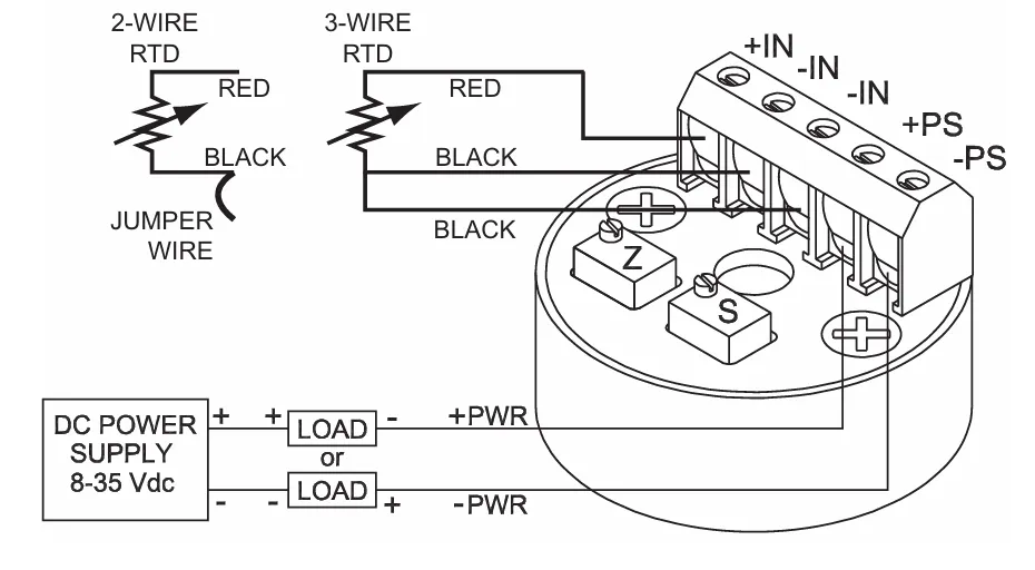
2-Wire RTD Transmitter Wiring
In a 2-wire system, both the excitation and sensing occur through the same pair of wires. A jumper is often installed internally or externally on the transmitter to compensate for the lead wire resistance. This type of connection is simple but less accurate than 3-wire configurations due to lead resistance errors.
3-Wire RTD Transmitter Wiring
The 3-wire RTD connection is commonly used in industrial applications. It helps eliminate the error caused by wire resistance by using one lead wire as a reference. The three wires are connected to the +IN, –IN, and COM terminals of the transmitter, depending on the vendor.
For both configurations, connect the DC power supply in series with the load and the transmitter across the (+PS) and (–PS) terminals. The RTD sensor wires are connected to the (+IN) and (–IN) terminals. The current output (4–20 mA) travels through the loop to the monitoring device or PLC input card.
Quick Wiring Steps:
- Connect the RTD sensor leads to the input terminals of the transmitter (+IN, –IN).
- Use shielded cables to reduce electrical noise.
- Connect the transmitter power terminals (+PS, –PS) in series with the power supply and PLC analog input card (if current loop input).
- Verify polarity and sensor wiring type (2-wire or 3-wire) and configure the transmitter accordingly.
Common Industrial Vendors Supporting RTD Transmitters:
- Rosemount – Models like 3144P and DIN rail transmitters
- ABB – TTH200, TTH300 series
- Siemens – SITRANS T series
- Yokogawa – YTA series
- Endress+Hauser – iTEMP TMT180, TMT82
How to Calibrate an RTD Temperature Transmitter
RTD temperature transmitters require periodic calibration to ensure accurate temperature-to-current signal conversion. The calibration process involves adjusting the transmitter’s Zero (Z) and Span (S) potentiometers to produce exactly 4 mA and 20 mA current outputs for specified resistance (ohmic) inputs that correspond to the temperature range.
RTD Transmitter Calibration Equipment and Setup
Before starting, ensure you have the following:
- RTD temperature transmitter (e.g., Model TX94A-2 or similar)
- DC power supply (24 VDC typical)
- Precision Decade Resistance Box or RTD/Temperature Simulator (e.g., CL511)
- Multimeter or loop calibrator to measure output current
- Copper test leads and appropriate connection terminals
Connect the transmitter to the calibration setup as shown in the wiring diagram. Use standard copper test leads for accurate resistance injection.
Step-by-Step RTD Transmitter Calibration Procedure
-
Identify Zero and Span Values:
Based on the model number, select the appropriate resistance values corresponding to the Zero (Z) and Span (S) points of the desired temperature range. -
Set Zero Point (4 mA):
Adjust the Decade Resistance Box to the selected Z value (e.g., 92.95 Ω). Measure the transmitter output current. Use the Z potentiometer to set the output to exactly 4.000 mA. -
Set Span Point (20 mA):
Adjust the Decade Resistance Box to the selected S value (e.g., 135.84 Ω). Now use the S potentiometer to adjust the output to exactly 20.000 mA. -
Repeat Adjustments:
Since Zero and Span adjustments are interactive, repeat the steps for Z and S settings until both values stabilize at 4.000 mA and 20.000 mA, respectively.
You may also use a temperature simulator to inject simulated RTD signals rather than ohmic values, as long as the calibration point values match the transmitter’s range.

Calibration Notes:
- Allow the transmitter to warm up for 10–15 minutes before calibration.
- Make sure your loop current measuring instrument is calibrated and accurate to ±0.01 mA.
- Avoid long lead wires between the Decade Box and transmitter input terminals.
Tip: This calibration process is valid for most industrial RTD transmitters from ABB, Rosemount, Siemens, and Yokogawa. Always refer to vendor-specific manuals for model-based resistance-to-temperature mappings.
Temperature Transmitter Troubleshooting Guide
Temperature transmitters may sometimes malfunction or produce incorrect readings. The following troubleshooting steps can help identify and resolve common issues related to wiring, power supply, and load resistance.
1. Incorrect or Fluctuating Readings
-
Check Wiring Connections:
Ensure all input and output wiring is correctly terminated. Refer to the transmitter’s wiring diagram (e.g., Figure 2-2 in the manual) and verify terminal assignments for RTD or thermocouple input and 4–20 mA output.
2. Loose or Broken Wires
-
Inspect Terminal Tightness:
Check each connection screw for tightness. Gently move each wire to detect any intermittent connection or signal fluctuation.
3. Power Supply and Load Resistance Issues
-
Measure Loop Resistance:
Use a multimeter to calculate the total resistance in the 4–20 mA current loop, excluding the transmitter and power supply. This includes:- All devices (e.g., indicators, PLC AI cards, barriers)
- Lead wire resistance
-
Calculate Maximum Loop Resistance:
Use the formula:Loop Resistance (max) = (Vsupply – 8V) ÷ 0.020A
Example: For a 24V power supply:
Loop Resistance = (24V – 8V) ÷ 0.020A = 800 Ω
-
Verify Power Supply Rating:
Ensure the power supply can deliver enough current. Each transmitter typically draws 24–28 mA. Multiply this by the number of transmitters to get the minimum power supply current rating.
Example: For 5 transmitters:Required Current = 5 × 28 mA = 140 mA minimum
Summary of Key Checks
- Verify all terminal connections are correct and secure
- Use a multimeter to check voltage and loop current
- Ensure total loop resistance does not exceed calculated max
- Confirm power supply can support all connected transmitters
If the issue persists after following these steps, consult the transmitter’s user manual or contact technical support for further assistance.
What is a Thermocouple Temperature Transmitter?
A Thermocouple Temperature Transmitter is a two-wire signal conditioning device designed to accept low-level millivolt signals from thermocouple sensors and convert them into a standardized 4–20 mA current output. This output is linearly proportional to the temperature measured by the thermocouple.
Since thermocouples generate very small millivolt signals (in the range of ±50 mV), these transmitters are essential for boosting the signal and transmitting it over long distances without significant loss or interference. The current signal can be easily sent over standard copper wires to PLCs, DCS systems, or remote indicators.
Supported Thermocouple Types and Operation
The transmitter typically supports multiple thermocouple types such as:
- Type J (Iron-Constantan)
- Type K (Chromel-Alumel)
- Type T (Copper-Constantan)
- Type E (Chromel-Constantan)
The output current begins at 4 mA for the lowest point in the configured temperature range and linearly rises to 20 mA at the highest point of the range. This allows easy integration with standard analog input modules and display instruments.
Typical Features
- Input: Millivolt signals from thermocouples
- Output: Standard 4–20 mA current signal
- Wiring: Two-wire loop powered (power and signal on same wires)
- Simple copper wire can be used for signal transmission
- Supports multiple thermocouple types with internal cold-junction compensation
Thermocouple transmitters are commonly mounted in field enclosures, connection heads, or DIN rails, providing reliable and noise-resistant analog signal transmission for process control and monitoring.
What is a Thermocouple Temperature Transmitter?
A Thermocouple Temperature Transmitter is a two-wire, loop-powered device that accepts low-level millivolt signals from thermocouples and converts them into a standardized 4–20 mA analog output signal. This signal is directly proportional to the temperature measured by the thermocouple.
Because thermocouples generate very small voltages (typically in millivolts), they are not ideal for direct transmission over long distances due to noise and signal loss. A thermocouple transmitter solves this by amplifying and converting the signal into a robust 4–20 mA signal that can be transmitted using standard copper cables.
Supported Thermocouple Types and Output Behavior
Most transmitters support common thermocouple types such as:
- Type J – Iron vs. Constantan
- Type K – Chromel vs. Alumel
- Type T – Copper vs. Constantan
- Type E – Chromel vs. Constantan
The transmitter outputs 4 mA at the low end of the configured temperature range and 20 mA at the high end. This proportional output allows integration with PLCs, DCS systems, or temperature indicators.
Key Features
- Converts millivolt signal to 4–20 mA current loop
- Supports multiple thermocouple types with cold-junction compensation
- Two-wire loop powered configuration (power and signal use same wires)
- Ideal for long-distance transmission using copper wire
- Compact, DIN rail or head-mount type designs available
Wiring and Installation
Wiring typically involves connecting the thermocouple sensor to the input terminals of the transmitter, and connecting the loop power supply and receiving device (e.g., PLC analog input) in series with the output terminals. Refer to the manufacturer's manual for polarity and grounding instructions.
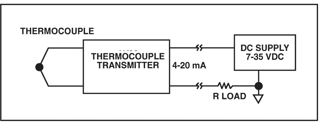
Thermocouple Temperature Transmitter Wiring
Wiring a thermocouple temperature transmitter involves two major connections: the power loop and the sensor input terminals. A standard 2-wire temperature transmitter uses the same pair of wires for both power and signal transmission (4–20 mA).
Power Supply and Load Connection
Connect a regulated DC power supply in series with the load (e.g., PLC analog input, DCS, or indicator) to the transmitter's power terminals:
- +PS — Positive terminal of the power supply
- –PS — Connect this to the load or analog input card
The current loop must complete the circuit by returning to the negative terminal of the power supply. The load device (monitoring instrument) can be placed on either side of the power leads depending on your system design.
Thermocouple Sensor Input Connection
Connect the thermocouple wires to the input terminals of the transmitter as follows:
- +IN — Positive thermocouple lead
- –IN — Negative thermocouple lead
Always ensure that the polarity of the thermocouple leads matches the input terminal labeling to avoid reverse signal issues. Use correct thermocouple extension wires (matching type) for accuracy.
Thermocouple Temperature Transmitter Calibration Procedure
Step 1: Preparing the Ice Bath (0°C Reference)
To ensure accurate calibration, a stable 0°C reference is often used via an ice bath:
- a) Fill a glass beaker with crushed ice made from distilled water.
- b) Add enough distilled water until the ice just becomes slushy. Avoid overfilling — the ice should not float.
- c) Insert the reference thermocouple into the center of the slush mixture.
Step 2: Initial Calibration Setup
Make sure the thermocouple wire type matches the calibration type of the transmitter (e.g., Type K, J, T, or E). Double-check polarity of the input connections. If using a simulator or calibrator, refer to the transmitter’s manual for correct zero and span values.
Step 3: Calibration Procedure
- Locate the Z (Zero) and S (Span) potentiometers on the temperature transmitter.
- Select the correct mV input values for zero and span as per your model specifications (e.g., from Table 3-1).
- Set your calibrated mV source to the zero (Z) value. Adjust the zero potentiometer until the output current reads exactly 4.000 mA.
- Set the mV source to the span (S) value. Adjust the span potentiometer until the current output reads exactly 20.000 mA.
- Repeat steps 3 and 4 as needed. There may be some interaction between the zero and span settings, so fine-tune both until both values stabilize at 4.000 mA and 20.000 mA respectively.
Note:
Use precision calibration tools like a thermocouple simulator (e.g., Model CL511) for better accuracy. Always allow the system to stabilize for a few seconds before recording readings.

Thermocouple Temperature Transmitter Troubleshooting Guide
Incorrect operation or malfunction of a thermocouple temperature transmitter may result from several common wiring or configuration issues. Follow the steps below to systematically diagnose and resolve the issue.
1. Reversed Polarity
A reversed polarity connection can result in abnormal readings, such as a drop in current when temperature increases. Check the following connections using the transmitter wiring diagram (e.g., Figure 2-6):
- a) Thermocouple wiring: Verify correct polarity at the input terminals.
- b) Power supply leads: Ensure the (+) and (–) terminals are properly connected.
- c) Monitoring instrument input polarity: Check for correct polarity and proper loop termination.
2. Loose or Broken Wires
Loose or damaged wiring can cause unstable or intermittent operation.
- Inspect each terminal for secure and tight connections.
- Gently move wires while monitoring output — any fluctuation may indicate a bad connection.
3. Load Resistance or Power Supply Issues
Too much resistance in the current loop or an underpowered power supply can result in reduced or unstable transmitter output.
a) Check Loop Resistance
- Measure total loop resistance, excluding transmitter and power supply.
- Include wire resistance and the input resistance of monitoring devices.
b) Calculate Maximum Allowable Resistance
Use this formula to determine the maximum loop resistance the system can tolerate:
Loop Resistance (max) = (Vsupply – 7V) / 0.020 A
Example: For a 24V DC supply,
Loop Resistance = (24V – 7V) / 0.020 A = 17V / 0.020 A = 850 ohms
c) Verify Power Supply Current Rating
Ensure your power supply can handle the total current draw:
- Each transmitter typically requires ~28 mA.
- For 5 transmitters: 5 × 28 mA = 140 mA. Your power supply should be rated at or above this value.
RTD/Thermocouple Signal Transmitter
An RTD/Thermocouple Signal Transmitter is a temperature signal conditioning device designed to work with both types of temperature sensors — RTDs and thermocouples. It receives the low-level signal from the sensor (millivolts for thermocouples or ohms for RTDs), processes it, and converts it into a standardized output such as 4–20 mA or digital communication (e.g., HART).
This type of transmitter helps eliminate signal loss, improves noise immunity, and simplifies the connection to automation systems like PLCs, DCS, or SCADA. Depending on the model, it can be single-channel or multi-channel and is available in head-mount, rail-mount, or field-mount formats.
Examples of RTD/Thermocouple Signal Transmitters
Here are some commonly used signal transmitters that support both RTD and thermocouple inputs. These models are widely used in industrial temperature measurement applications:
- Rosemount 644 – Universal temperature transmitter for RTD and thermocouple input with HART communication.
- ABB TTH300 – Head-mount temperature transmitter supporting multiple sensor types and communication protocols like HART and PROFIBUS.
- Siemens SITRANS TH300 – Compact transmitter compatible with various RTDs and thermocouples, supporting advanced diagnostics.
- WIKA T32 – High-accuracy universal transmitter for both sensor types, with SIL certification and configurable via PC software.
- Honeywell STT750 – Smart temperature transmitter supporting dual input, RTD/Thermocouple, with digital output options.
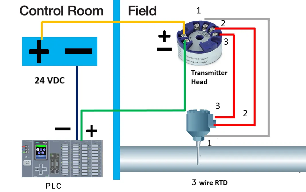
RTD Transmitter Wiring to PLC (3-Wire Connection)
An RTD (Resistance Temperature Detector) sensor typically uses a 3-wire configuration to minimize the effect of lead wire resistance. The RTD is connected to a temperature transmitter which converts the resistance signal into a standard 4–20 mA output signal. This analog signal is then fed into the PLC’s analog input module.
Wiring Explanation:
- The RTD sensor has three wires: two on one side (for compensation) and one on the opposite side.
- The transmitter receives 24V DC loop power. The positive terminal of the power supply connects to the transmitter's + terminal.
- The transmitter’s – terminal connects to the PLC analog input + (AI+).
- The analog input – (AI–) connects to the 0V (negative) terminal of the power supply to complete the loop.
- A junction box or screw terminal block may be used between the field and panel for better organization.
Thermocouple Transmitter Wiring to PLC (K-Type Example)
A thermocouple (such as K-type) generates a millivolt signal based on temperature difference between its two junctions. This small signal is processed by a temperature transmitter which converts it into a robust 4–20 mA signal. The transmitter is then connected to a PLC analog input for monitoring and control.
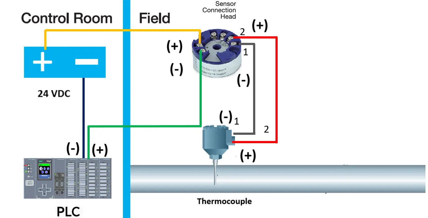
Wiring Explanation:
- The thermocouple is directly wired to the transmitter’s thermocouple input terminals (observe polarity).
- The transmitter is loop-powered with a 24V DC supply. The positive terminal of the power supply is connected to the transmitter’s + terminal.
- The transmitter’s – terminal connects to the PLC analog input + (AI+).
- The analog input – (AI–) connects to the 0V (negative) of the power supply.
- Junction boxes may be used for wiring terminations, and correct polarity must be maintained to avoid reading errors.
Example transmitter: Siemens SITRANS T (supports thermocouple input including K-type)