Temperature Transmitter – Working Principle, Types & Applications
Published on July 17, 2024 | Category: introductionShare this Page:
A temperature transmitter is an essential component in industrial automation used to convert temperature sensor signals (like RTD or thermocouple outputs) into standardized output signals such as 4–20 mA or digital protocols. These devices ensure accurate and noise-resistant transmission of temperature readings over long distances to PLCs, DCS, or control panels.
Typically installed in harsh environments, temperature transmitters enhance signal quality, reduce wiring complexity, and improve process reliability. Based on design and use, they are classified into 2-wire, 3-wire, and 4-wire transmitters. They can be analog or smart (HART/Fieldbus-enabled), and are commonly used in oil & gas, chemical, HVAC, food processing, and power plants.
This page explores the working principle of temperature transmitters, different types, key applications, and best practices for selection and installation.
What is a Temperature Transmitter?
A temperature transmitter is an industrial device used to convert the signal from a temperature sensor—such as an RTD (Resistance Temperature Detector) or thermocouple—into a standardized 4–20 mA or digital output signal. This helps transmit accurate temperature data to controllers, PLCs, or DCS systems over long distances.
The most common sensor inputs for temperature measurement are Resistance Temperature Detectors and thermocouples . Additional inputs are millivolt (mV), ohm, and potentiometer.
Transmitters accept different input signals (such as RTDs or thermocouples), process them internally, and output a strong, noise-resistant signal. Depending on the model, they can also provide digital communication using protocols like HART or Fieldbus.
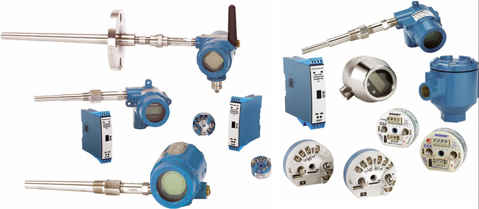
Temperature transmitters are available in different housing styles and materials. They can be mounted:
- Directly on the sensor or thermowell at the process measurement point
- Remotely in separate enclosures
Many modern transmitters support both local and remote configuration, offer onboard displays for local indication, and include optional features such as diagnostics, wireless transmission, and signal filtering. The choice of transmitter depends on the environment, accuracy needs, and communication requirements.

Working Principle of a Temperature Transmitter
A temperature transmitter functions by converting the sensor signal (from RTDs or thermocouples) into a stable and standardized output, typically 4–20 mA or digital. The design and performance of this process depend heavily on the manufacturer’s engineering expertise and proprietary signal processing techniques.
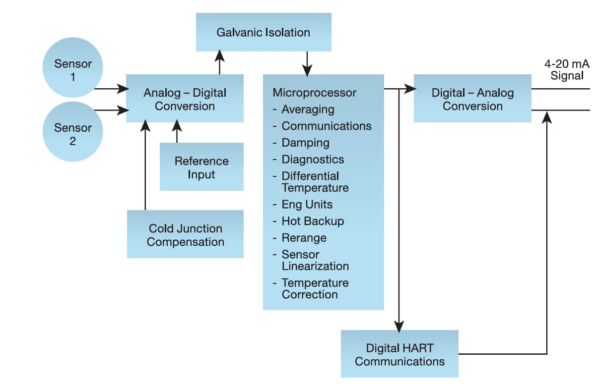
High-quality temperature transmitters are designed to deliver high accuracy, long-term stability, and noise immunity. They typically consist of three key internal subsystems:
- 1. Input Subsystem: This part captures the raw signal from the sensor and converts it into a digital value using an Analog-to-Digital (A/D) converter.
- 2. Signal Conditioning Subsystem: This block processes the digital signal through filtering, linearization, and compensation. It mathematically manipulates the signal to accurately represent the temperature.
- 3. Output Subsystem: The conditioned signal is converted back into an analog format using Digital-to-Analog (D/A) conversion and is transmitted as a robust 4–20 mA or digital communication signal (e.g., HART).
The performance of a transmitter depends on how well these three subsystems work together to handle noise, ensure stability, and maintain signal integrity. Modern transmitters may also include self-diagnostics and temperature drift compensation for long-term reliability.
RTD Inputs and Outputs
Resistance Temperature Detectors (RTDs) operate on the principle that the electrical resistance of certain metals increases as temperature rises—a behavior known as thermal resistivity. By measuring the resistance of the RTD element, the corresponding temperature can be accurately determined.
RTDs are made from a resistive material (most commonly platinum) and are constructed with attached wire leads, typically enclosed in a protective sheath. Other materials like copper or nickel may also be used, but platinum is preferred for its high accuracy and stability over a wide temperature range.
Standard platinum RTDs are available with nominal resistances of 100 Ω to 1000 Ω. These sensors come in 2-wire, 3-wire, or 4-wire configurations, each offering varying levels of compensation for lead wire resistance and accuracy.
Thermocouple Inputs and Outputs – Working Principle and Types
A thermocouple (T/C) is a temperature sensing device made by joining two dissimilar metal wires at both ends. When there is a temperature difference between the two junctions, a voltage (EMF) is generated—this is known as the Seebeck effect.
The hot junction is placed at the measurement point inside a protective sheath, while the cold junction (reference junction) is located externally in a transmitter, input card, or signal conditioner where the voltage is measured.
Transmitters or control systems read this voltage and convert it to a temperature value. Most industrial transmitters support standard thermocouple types like J, K, T, E, R, S, B, C, and N. Type N is often used as an alternative to R and S due to its enhanced stability in high-temperature environments.
Types of Temperature Transmitters
Temperature transmitters come in various types depending on their construction, output signal, mounting method, and communication capabilities. Choosing the right type depends on application requirements such as accuracy, distance, environment, and signal integration with control systems.
1. Based on Signal Output
- Analog Transmitters (4–20 mA): Convert sensor signal to a standard current signal for long-distance transmission with good noise immunity.
- Digital/Smart Transmitters: Use digital protocols like HART, Profibus, or Foundation Fieldbus for more advanced communication and diagnostics.
2. Based on Sensor Input
- RTD Transmitters: Designed to work with RTDs like Pt100, Pt1000 etc., offering high accuracy and linearity.
- Thermocouple Transmitters: Accept thermocouple inputs (Types J, K, T, etc.) and often include cold junction compensation.
- Universal Transmitters: Accept both RTD and thermocouple inputs with selectable input types and ranges.
3. Based on Mounting Style
- Head-Mounted Transmitters: Compact units installed directly inside the sensor terminal head (DIN Form B).
- Rail-Mounted Transmitters: DIN rail-mounted units used in control panels for centralized signal processing.
- Field-Mounted Transmitters: Rugged, weatherproof enclosures for harsh environments, often with display and configuration buttons.
4. Based on Wire Configuration
- 2-Wire Transmitters: Power and signal are combined in one loop—simplest and most common in industry.
- 3-Wire and 4-Wire Transmitters: Provide better compensation for lead resistance, typically used in precision applications.
Single, Dual, and Multipoint Temperature Transmitters
Most temperature transmitters are designed to handle at least one sensor input. These are known as single-input transmitters and are widely used in standard process control applications.
Some advanced models support dual sensor inputs, allowing them to accept data from two sensors simultaneously. This dual-input feature offers benefits such as:
- Sensor redundancy – for reliability in critical measurements
- Sensor drift detection – improves accuracy over time
- Average or differential temperature measurement – useful in heat exchangers and thermal profiling
In addition, multipoint (multi-input) transmitters can accept up to eight temperature sensor inputs. These are known as high-density transmitters and are ideal for compact spaces or clustered installations, such as:
- Boiler tube monitoring
- Reactor vessel profiling
- Large furnace or chamber temperature mapping

Selecting the Right Temperature Transmitter – Key Factors & Recommendations
Choosing a suitable temperature transmitter involves more than matching sensor types. You need to consider signal reliability, environmental conditions, mounting style, and the features required for your process. Transmitters vary widely in capability, from basic analog models to smart, feature-rich versions with advanced diagnostics and digital protocols.
Modern transmitters are often built on proprietary engineering and refined signal processing techniques, making them capable of delivering high stability, accuracy, and resistance to noise. A smart transmitter enhances signal quality through features such as isolation, linearization, cold-junction compensation, and filtering.
Transmitters may be installed locally with the sensor (e.g., inside a connection head) or remotely in control cabinets using DIN rail mounting. Housings come in various materials, including plastic, aluminum, or stainless steel, and are selected based on ambient conditions or explosion-proof requirements.
What to Look for When Selecting a Temperature Transmitter
- Sensor Compatibility: RTD (e.g., Pt100) or thermocouple types (J, K, etc.)
- Signal Output: Analog (4–20 mA) or Digital (HART, Fieldbus, Profibus)
- Input Configuration: Single, dual, or multipoint input capability
- Mounting Type: Head-mount, panel-mount (DIN rail), or field-mount
- Protection Rating: IP65/IP67, flameproof (Ex d), or intrinsically safe (Ex ia)
- Smart Features: Local display, diagnostics, sensor drift detection, and stability tuning
- Certifications: SIL, ATEX, IECEx, or FM-approved models for critical safety applications
For specialized applications, consider models with extended diagnostics, multi-sensor input, or wireless communication. Also evaluate the host system (PLC, DCS) for compatibility and integration options.
- Single, Dual & Multipoint Configurations: Understand the benefits of using one, two, or multiple sensor inputs in a transmitter—ideal for redundancy, differential, or multi-zone measurement.
- Output Signal Options: Explore available signal formats such as 4–20 mA analog, HART, Profibus, or wireless, depending on your control system integration needs.
- Performance Characteristics: Evaluate the transmitter’s accuracy, repeatability, and response time, which impact process reliability and quality control.
- Stability Considerations: Learn how long-term signal stability reduces maintenance and recalibration efforts, especially in critical or remote applications.
- Filtering Algorithms: Review intelligent filtering features that reduce noise, eliminate spikes, and stabilize the measurement signal during process fluctuations.
- Built-in Diagnostics: Identify transmitters with self-diagnostics, sensor failure detection, and health monitoring for predictive maintenance and troubleshooting.
- Housing & Mounting Variants: Choose from head-mounted, DIN rail, or field-mounted transmitters based on installation location, protection rating, and space constraints.
- Safety-Certified Transmitters: For hazardous or safety-critical environments, select transmitters with SIL, ATEX, IECEx, or FM certifications.
- Transmitter vs. Direct Wiring: Understand the advantages of using a transmitter instead of directly wiring sensors to control systems—better signal integrity, fewer wires, and longer distances.
What is HART Protocol in Temperature Transmitters?
The HART (Highway Addressable Remote Transducer) protocol is a globally recognized digital communication standard used with smart temperature transmitters. It allows a digital signal to be superimposed on the traditional analog 4–20 mA current loop, enabling two-way data communication over the same pair of wires.
This dual transmission means users can access valuable device information—such as configuration settings, calibration data, diagnostics, and alerts—without disrupting the main analog output used for control or monitoring.
Key Advantages of Using HART Protocol:
- Remote Configuration: Devices can be set up or reprogrammed remotely using handheld communicators or software.
- Advanced Diagnostics: Live sensor health and fault data help in predictive maintenance and reduce downtime.
- Improved Process Visibility: Continuous data collection via DCS or asset management systems enhances control.
- Cost Savings: Minimizes wiring, reduces manual work, and extends maintenance cycles.
With HART protocol, data from multiple field transmitters can also be collected using HART multiplexers connected to a DCS or an Asset Management System. This enhances efficiency and supports plant-wide digitalization.

Difference Between Temperature Transmitter and PLC Temperature Module
In industrial automation systems, both temperature transmitters and PLC temperature input modules are used to acquire temperature data from sensors like RTDs and thermocouples. However, their roles, capabilities, and installation requirements differ significantly.
| Feature | Temperature Transmitter | PLC Temperature Module |
|---|---|---|
| Purpose | Converts sensor signal (RTD/Thermocouple) into standard signal (4–20 mA or digital). | Directly reads sensor input and processes it within the PLC system. |
| Signal Output | Analog (4–20 mA), HART, or digital protocols. | Digital data available to the PLC CPU for logic/programming. |
| Mounting | Field-mounted (head-mounted, DIN-rail, or remote housing). | Rack-mounted inside the PLC panel. |
| Wiring Distance | Ideal for long distances; analog signal travels over shielded cable. | Best suited for short cable runs due to sensor signal noise sensitivity. |
| Cost | Moderate to high depending on smart features and housing. | Cost-effective when many channels are needed in one PLC system. |
| Advanced Features | Diagnostics, sensor drift detection, cold-junction compensation, filtering. | Basic signal acquisition; advanced processing depends on PLC program. |
| Redundancy & Safety | Supports sensor redundancy, SIL-rated models available. | May lack advanced safety diagnostics unless PLC supports it. |
Conclusion: Choose a temperature transmitter when accuracy, long-distance signal integrity, or smart diagnostics are required. Use a PLC temperature module when the sensor is near the PLC panel and cost-efficiency is a priority.