What is a Thermocouple? | Types, Working Principle & Applications
Published on July 16, 2024 | Category: introductionShare this Page:
Thermocouples are valued for their wide temperature range, fast response, rugged design, and self-powered capability—meaning they do not require an external power supply. Their simplicity and compatibility make them easy to interface with PLCs and industrial control systems. This page is ideal for students, engineers, and technicians looking to understand thermocouples for practical applications, instrumentation setup, or interview preparation.
This page explains what a thermocouple is, how it works, and where it is used in industrial applications. A thermocouple is a temperature-sensing instrument widely used across industries like steel, glass, petrochemicals, cement, and power generation. It works by converting thermal energy into electrical energy, producing a millivolt (mV) output that can be read using a voltmeter or multimeter.
What is a Thermocouple?
A thermocouple (T/C) is a type of temperature sensor made by joining two dissimilar metal wires at one end. This joined point is called the sensing or measuring junction. When there is a temperature difference between this junction and the other (reference) end, a small voltage is generated due to a principle called the Seebeck effect.
This voltage is very small, usually in the range of millivolts (mV), and it changes with the temperature difference between the two ends. The output can be easily measured using a voltmeter, multimeter, or connected to a PLC/temperature transmitter for further processing.
Thermocouples are widely used in industries because they are simple, cost-effective, self-powered (no need for an external supply), and suitable for a wide temperature range.
Thermocouple Working Principle
A thermocouple works on the basic principle that a voltage is generated when two different metals are joined together and exposed to a temperature difference between the junctions. This generated voltage (measured in millivolts) can be used to determine temperature. The operation of a thermocouple is based on three thermoelectric effects: Seebeck effect, Peltier effect, and Thomson effect.
In a thermocouple circuit, one end of the dissimilar metal wires is placed in the process (called the hot junction), and the other end remains at a known reference temperature (called the cold junction). When there is a temperature difference between the two ends, a small voltage is generated across the circuit. This voltage is directly related to the temperature difference and is used to measure temperature accurately.
The basic working principle of a thermocouple is based on three key thermoelectric effects: the Seebeck effect, Peltier effect, and Thomson effect. These effects describe how electrical voltage or heat is generated when different materials experience temperature gradients.
The combined behavior of Seebeck, Peltier, and Thomson effects enables the functioning of thermocouples:
Seebeck Effect in Thermocouples
The Seebeck effect is the fundamental principle behind thermocouple operation. It was discovered by German physicist Thomas Johann Seebeck. According to the Seebeck effect:
“When two dissimilar metals are joined at two junctions, and one of the junctions is heated, an electromotive force (EMF) is generated due to the temperature difference. This voltage causes a current to flow through the circuit.”
In a thermocouple, one junction is the hot junction (placed in the process), and the other is the cold junction (reference end). The resulting voltage (called Seebeck voltage or thermoelectric EMF) is proportional to the temperature difference between these two points and is measured in millivolts (mV).
Peltier Effect in Thermocouples
The Peltier effect, discovered by Jean Peltier, is the reverse of the Seebeck effect. It involves the absorption or release of heat when an electric current passes through the junction of two different conductors.
“When current flows through a junction formed by two dissimilar metals or semiconductors, heat is either absorbed at one junction or released at the other.”
Though not directly responsible for sensing in thermocouples, the Peltier effect is important in understanding thermoelectric heat transfer and material behavior at junctions.
Thomson Effect in Thermocouples
The Thomson effect, discovered by William Thomson (Lord Kelvin), describes how heat is absorbed or released along a single conductor when both a temperature gradient and current are present.
“The heating or cooling of a conductor occurs when an electric current flows through it, due to a temperature difference along its length.”
This effect occurs within a single material and plays a minor role in the total voltage developed by a thermocouple. It is used in high-accuracy thermoelectric measurements.
Together, these three effects explain how thermocouples generate a voltage signal without any external power. Among them, the Seebeck effect plays the most important role in the actual temperature sensing process, while the Peltier and Thomson effects help us understand and refine temperature behavior in materials.

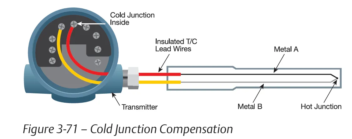
What is Cold Junction Compensation (CJC) in Thermocouples?
Thermocouples measure temperature by creating a small voltage based on the difference between two junctions: the hot junction (in the process) and the cold junction (reference end). However, they only give the temperature difference — not the actual temperature at the hot end.
To calculate the correct temperature at the hot junction, we must first know the temperature at the cold junction. This process is called Cold Junction Compensation (CJC).
CJC is usually done by the temperature transmitter, PLC input module, or signal conditioner. These devices have built-in sensors like a thermistor, RTD, or temperature-sensing IC placed near the cold junction to measure its temperature.
The CJC sensor is often mounted on an isothermal terminal block (usually made of copper) to ensure stable temperature readings. The closer and more accurate the CJC measurement is, the more precise the final temperature calculation will be.
Key Point: Without CJC, thermocouples cannot give accurate temperature readings because they only measure voltage based on the difference — not absolute values. CJC bridges that gap by adding back the cold junction temperature.
Construction of Thermocouple
A thermocouple is constructed by joining two wires made of different metals or alloys, depending on the required temperature range and application. The quality of these materials and the precision of the junction play a key role in performance and accuracy.
The process begins by selecting the correct material combination based on the type of thermocouple being manufactured. Some common thermocouple types and their material combinations are:
- Type K: Nickel-Chromium or Nickel-Aluminum (−200°C to 1350°C)
- Type J: Iron and Constantan (−40°C to 750°C)
- Type T: Copper and Constantan (−200°C to 350°C)
- Type E: Nickel-Chromium and Constantan (−200°C to 900°C)
- Type N: Nickel-Chromium-Silicon and Nickel-Silicon-Magnesium (−270°C to 1300°C)
- Type R, S, B: Platinum and Rhodium in various combinations (0°C to 1800°C)
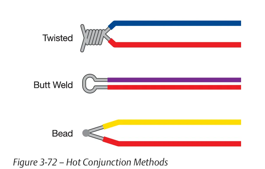
After selecting the wire materials, they are joined at one end to form the hot junction. This can be done using methods such as welding, brazing, soldering, clamping, or twisting. For industrial-grade and high-accuracy thermocouples, a bead weld is often used to form a solid and sound junction.
The hot junction must be:
- Mechanically strong and durable
- Electrically continuous with minimal resistance
- Free from contamination due to welding/brazing materials
Premium-grade thermocouples use high-purity metals and controlled welding environments to ensure long life and consistent readings, especially in harsh industrial environments.
Types of Thermocouple Junctions
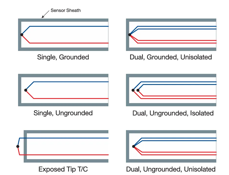
Thermocouple junctions are constructed in various configurations to suit different applications. Each type affects the sensor’s response time, electrical isolation, and resistance to noise or environmental conditions. The most common types include Grounded, Ungrounded, and Exposed Junctions. Dual thermocouple types may also be isolated or unisolated.
1. Grounded Junction
In a grounded thermocouple, the sensing (hot) junction is directly connected to the metal sensor sheath. This ensures excellent thermal conductivity and results in the fastest response time. However, because the junction is electrically connected to the sheath, it can become vulnerable to electrical noise.
To reduce this interference, the measurement system (transmitter or I/O card) must offer good galvanic isolation. One disadvantage of grounded junctions is that they may be more susceptible to chemical or electrical poisoning over time.
2. Ungrounded Junction
In an ungrounded thermocouple, the hot junction is completely isolated from the sheath and surrounded by insulating material. This provides better electrical noise immunity than grounded junctions and makes it suitable for electrically noisy industrial environments.
The trade-off is that ungrounded junctions have a slower response time compared to grounded types, since the thermal path is longer and less conductive.
3. Exposed Junction
In an exposed junction thermocouple, the sensing tip is extended beyond the sheath and is directly exposed to the environment. This results in the fastest response time among all junction types. A protective seal is often applied just inside the sheath to block moisture and contaminants.
These thermocouples are best suited for use in clean, non-corrosive gases, such as in air ducts or lab environments. They are not recommended for liquid or corrosive applications as the exposed junction can degrade quickly.
Dual Junctions: Isolated vs. Unisolated
Dual thermocouples consist of two independent sensing elements within the same sheath. These can be configured as:
- Dual, Grounded, Unisolated: Both elements share the same grounded junction; fast but not electrically isolated.
- Dual, Ungrounded, Isolated: Two ungrounded elements, each electrically separated; used for redundant or critical measurements.
- Dual, Ungrounded, Unisolated: Two ungrounded elements that share a common circuit path; partially isolated.
Choosing the right junction type depends on the application's requirements for response time, electrical isolation, and environmental conditions.
Type J Thermocouple – Iron and Constantan
Type J thermocouples are commonly used for general low-temperature applications in the range of –40°C to 750°C. They are made from a combination of iron (positive) and constantan (negative). With a sensitivity of about 50 µV/°C, they offer good performance in vacuum, inert, or reducing environments.
Type J performs well between 149°C and 427°C, but may become brittle at sub-zero temperatures. Above 538°C, iron oxidizes rapidly, reducing lifespan and accuracy. Operation near the Curie point of iron (770°C) can permanently change calibration.
Type T Thermocouple – Copper and Constantan
Type T thermocouples are often used in laboratory and cryogenic environments, with a temperature range of –200°C to 350°C. They are made from copper (positive) and constantan (negative), and offer a sensitivity of 38 µV/°C.
Type T is known for its excellent moisture resistance and good linearity, making it suitable for oxidizing, reducing, and vacuum atmospheres. It is ideal for precise low-to-medium temperature measurements.
Type E Thermocouple – Chromel and Constantan
Type E thermocouples are used for high-sensitivity applications, especially in cryogenics. They operate from –200°C to 900°C and are made of Chromel (positive) and Constantan (negative).
With a sensitivity of 68 µV/°C, Type E offers the highest voltage output per °C among standard thermocouples. It is suitable for oxidizing or inert atmospheres, but can drift more than other types and is not recommended for temperatures below 0°C in critical applications.
Type N Thermocouple – Nicrosil and Nisil
Type N thermocouples are designed for stability in high-temperature environments like aerospace, nuclear, and furnace systems. The temperature range is –270°C to 1300°C. They are made from Nicrosil (positive) and Nisil (negative) alloys.
With a sensitivity of 39 µV/°C, Type N offers excellent thermoelectric stability, especially in oxidizing atmospheres. However, it is not suitable for vacuum or alternating reducing/oxidizing environments. It performs comparably to noble metal types (R/S) up to 1200°C.
Type R Thermocouple – Platinum (13%) and Rhodium
Type R thermocouples are made from Platinum-13% Rhodium (positive) and Platinum (negative). They are suitable for high-temperature industrial applications such as kilns, furnaces, and glass or steel processing.
They operate in the range of –50°C to 1768°C with a sensitivity of around 10 µV/°C. Due to the high cost of platinum, Type R is reserved for situations where high accuracy and stability are essential.
Proper installation with ceramic insulators and non-metallic protection tubes is critical to prevent contamination and ensure longevity.
Type S Thermocouple – Platinum (10%) and Rhodium
Type S thermocouples are made from Platinum-10% Rhodium (positive) and Platinum (negative). Like Type R, they are used in extreme temperature environments, especially in laboratory standards and calibration setups.
With a working range of –50°C to 1768°C and sensitivity of 10 µV/°C, Type S is also used to define the International Temperature Scale between 630.5°C and 1064.43°C.
They require clean, oxidizing atmospheres and long-term use can lead to calibration drift due to rhodium diffusion and grain growth.
Type B Thermocouple – Platinum (30%) and Rhodium (6%)
Type B thermocouples are made from Platinum-30% Rhodium (positive) and Platinum-6% Rhodium (negative), offering one of the highest temperature ranges among all thermocouples: 0°C to 1820°C.
They are best used in clean air or oxidizing atmospheres and should not be exposed to reducing environments. Their higher rhodium content reduces grain growth and enhances long-term stability compared to Type R and S.
Commonly used in ceramic, glass, metallurgy, and aerospace industries, Type B is ideal where extreme and consistent high temperatures are present.
Summary Table of Thermocouple Types
This table provides a quick comparison of the most commonly used thermocouple types based on their material composition, temperature range, sensitivity (in µV/°C), and typical industrial applications. It helps users select the appropriate thermocouple type depending on their measurement needs and environmental conditions.
| Type | Material Composition | Temperature Range (°C) | Sensitivity (µV/°C) | Use Case |
|---|---|---|---|---|
| K | Chromel / Alumel | –200 to 1350 | ~41 | General-purpose, furnaces, oxidizing environments |
| J | Iron / Constantan | –40 to 750 | ~50 | Low temp, vacuum/inert gas, oxidizing limit |
| T | Copper / Constantan | –200 to 350 | ~38 | Lab, cryogenics, moisture resistance |
| E | Chromel / Constantan | –200 to 900 | ~68 | Cryogenics, high sensitivity, oxidizing atmosphere |
| N | Nicrosil / Nisil | –270 to 1300 | ~39 | Aerospace, nuclear, oxidizing only |
| R | Platinum-13% Rhodium / Platinum | –50 to 1768 | ~10 | Industrial high-temp (kilns, furnaces) |
| S | Platinum-10% Rhodium / Platinum | –50 to 1768 | ~10 | Lab calibration, precise high-temp use |
| B | Pt-30% Rhodium / Pt-6% Rhodium | 0 to 1820 | ~10 | Very high-temp, clean oxidizing atmospheres |
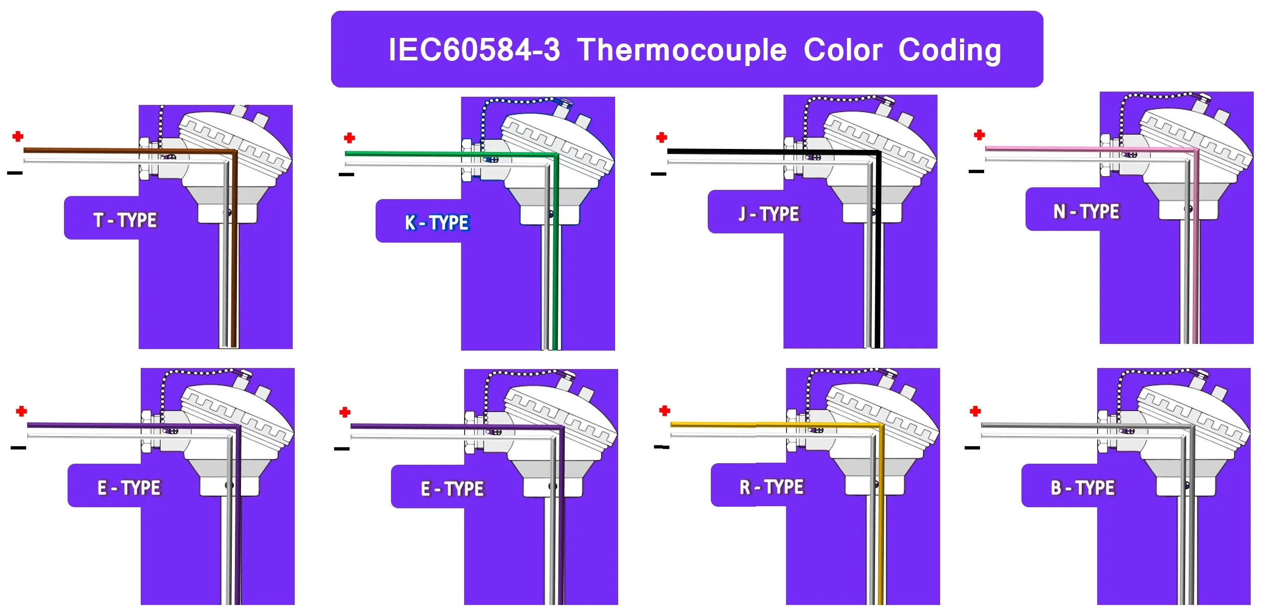
Thermocouple Lead Wire Color Standards
Thermocouple wires are color-coded to help technicians identify polarity and thermocouple type during installation and maintenance. These wires consist of two conductors: one positive and one negative, each with colored insulation. The color coding is standardized differently across regions, depending on the specification followed.
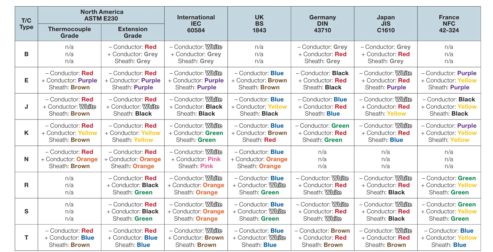
The Seebeck effect means correct polarity is crucial for accurate measurement. Connecting leads incorrectly may reverse readings or damage equipment. Refer to the table or chart below for different color coding standards such as:
- ASTM E230 (North America)
- IEC 60584 (International)
- BS 1843 (United Kingdom & Czech Republic)
- DIN 43710 (Germany)
- JIS C1610 (Japan)
- NFC 42-324 (France)
Most commonly in North America, the negative conductor is colored red. Under the IEC standard, the negative conductor is usually white. Always verify the standard being used at your site to avoid mismatches in connection or troubleshooting errors.
Applications of Thermocouples
Thermocouples are widely used temperature sensors in industrial and scientific applications due to their broad temperature range, fast response time, rugged construction, and low cost. They convert temperature differences into millivolt signals based on the Seebeck effect, making them ideal for environments where real-time temperature monitoring and control are essential.
Common Applications of Thermocouples:
- Industrial Furnaces & Kilns: Monitor high-temperature processes in cement, ceramics, steel, and glass manufacturing.
- Power Plants: Measure temperature in boilers, steam lines, and turbines for safety and efficiency.
- Petrochemical Plants: Used in refineries for temperature control in reactors, heaters, and pipelines.
- Food & Beverage Industry: Ensure safe cooking, pasteurization, freezing, and preservation processes.
- HVAC Systems: Monitor air and gas temperature in heating, ventilation, and air conditioning systems.
- Automotive Industry: Measure exhaust gas, engine block, and catalytic converter temperatures.
- Aerospace Applications: Measure surface and engine temperatures in aircraft and rockets.
- Medical Equipment: Embedded in autoclaves, incubators, and cryogenic systems for precise thermal control.
- Laboratory Testing: Used in scientific experiments for accurate temperature measurement in controlled environments.
- Renewable Energy: Monitor temperature in solar thermal plants, biomass boilers, and geothermal systems.
Thanks to their simplicity, versatility, and self-powered operation, thermocouples remain one of the most preferred temperature sensors across both legacy and modern control systems.
How to Install a Thermocouple in the Field
Proper installation of a thermocouple is essential for accurate and reliable temperature measurement. Whether it's used in a process plant, furnace, HVAC duct, or pipeline, the installation process must consider junction type, sensor placement, wiring practices, and environmental conditions.
Step-by-Step Thermocouple Installation Procedure:
- Identify Measurement Point: Select a location where accurate temperature reading is needed — such as inside a pipe, vessel, kiln, or duct. Avoid placing near walls or corners to prevent heat reflection errors.
- Choose the Right Thermocouple Type: Select based on the temperature range, environment (oxidizing, reducing, corrosive), and required response time (e.g., Type K, J, T, etc.).
- Select Sheath & Junction Type: Based on application needs, use grounded (fast response), ungrounded (noise-free), or exposed tip (quick response in clean gas).
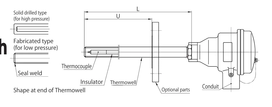
- Insert Sensor Properly: Mount the thermocouple so that the hot junction (measuring tip) is directly in contact with the process medium. For pipes or tanks, use a thermowell if needed.
- Use a Thermowell (if required): In harsh, high-pressure, or corrosive environments, insert the thermocouple into a thermowell to protect the sensor and ease replacement.
- Secure with Fittings: Use compression fittings, flanges, or threaded connections to fix the sensor in place. Ensure the sensor does not move or vibrate.
- Route Extension Wires: Use matching thermocouple extension cables. Avoid mixing wire types or polarity. Keep cables away from high-voltage sources to reduce electrical noise.
- Cold Junction Compensation (CJC): Install the cold junction at a known temperature reference point or use transmitters with built-in CJC circuits for accurate output.
- Connect to Measuring Device: Connect wires to PLC, transmitter, or temperature controller. Observe correct polarity: the negative lead is usually red (ASTM) or white (IEC).
- Test and Validate: Once installed, measure resistance or mV output to verify sensor continuity and check that readings are stable and accurate.
Important Installation Tips:
- Always match thermocouple type to extension cable type (e.g., Type K sensor → Type K cable).
- Avoid long runs of thermocouple cable — use transmitters or signal conditioners near the sensor.
- Shielded cables or twisted pairs can help minimize EMI (electromagnetic interference).
- Follow local safety, grounding, and IP protection guidelines for hazardous areas.
Proper thermocouple installation ensures accurate temperature measurement, extended sensor life, and process reliability.

How to Test a Thermocouple
Thermocouples generate a small DC voltage (in millivolts) proportional to the temperature difference between their hot and cold junctions. If your system isn’t reading temperature correctly, follow these simple steps to test your thermocouple for accuracy and reliability.
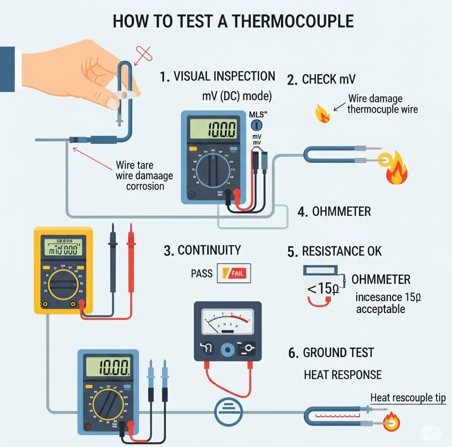
Step 1: Visual Inspection
- Inspect the thermocouple wire and junction for visible damage.
- Check for corrosion, broken wires, insulation wear, or bent tips.
Step 2: Check Thermocouple Output in mV (Millivolts)
Use a multimeter or voltmeter set to DC millivolts mode.
- Connect the multimeter probes to both thermocouple wires.
- Apply heat to the tip (hot junction) using a heat gun or flame.
- The voltage should increase proportionally with temperature.
- Compare the mV reading with a standard thermocouple reference table to verify accuracy.
Step 3: Check Continuity of the Thermocouple
Set the multimeter to continuity mode:
- Place the probes on both thermocouple wires.
- If there is no continuity (open circuit), the thermocouple is broken and should be replaced.
Step 4: Check Resistance of the Thermocouple
Use the ohmmeter function on your multimeter:
- Measure resistance across both thermocouple wires.
- A working thermocouple typically shows a very low resistance (below 15 ohms).
- If resistance is significantly higher, the thermocouple may be degraded.
Step 5: Ground Test of the Thermocouple
To check for an accidental ground fault:
- Set your multimeter to continuity mode.
- Place one probe on a thermocouple wire and the other on a grounded surface.
- If continuity is detected, the thermocouple may be shorted and should not be used.
Step 6: Heat Test After Removal
- Remove the thermocouple from the circuit.
- Heat the sensing tip while observing the mV output on a multimeter.
- If the reading doesn’t increase steadily, or remains erratic, the thermocouple is faulty.
By performing these simple checks, you can easily identify if your thermocouple sensor is working correctly or needs replacement. Regular testing helps avoid process faults and ensures measurement reliability.
Thermocouple – Frequently Asked Questions (FAQs)
Q1. What is the difference between a Mineral Insulated (MI) and a fabricated sheath?
A: MI thermocouples are flexible and robust, ideal for installations in confined or curved paths. Fabricated sheaths are rigid and best suited for straight, fixed applications.
Q2. How accurately can I measure temperature using a standard sensor?
A: Standard accuracy is ±2.5°C for common thermocouples and ±0.5°C for Platinum Resistance Thermometers (PRTs). For higher accuracy, sensors like Type T (±0.5°C) or 4-wire PRTs (±0.2°C) are recommended. Accuracy depends on temperature and sensor quality.
Q3. How do I choose between a thermocouple and a PRT?
A: The decision depends on required accuracy, temperature range, sensor response time, and physical size. Thermocouples are better for high temperatures and quick response, while PRTs are best for high precision and stability.
Q4. What if my thermocouple is far from the controller?
A: Long wire lengths increase loop resistance, which can introduce error. Keep total loop resistance below 100 Ohms. Use a 4–20 mA transmitter near the sensor for longer distances and better signal integrity over cheaper copper wire.
Q5. Should I choose a Type K or Type N thermocouple?
A: Type N offers better long-term stability and performance at high temperatures compared to Type K. The choice depends on your process conditions and environment.
Q6. Does the choice of sheath material matter?
A: Yes. Correct sheath material enhances durability and chemical resistance. For example, Inconel or stainless steel are selected based on corrosion resistance and temperature exposure.
Q7. Are there temperature sensors other than thermocouples and PRTs?
A: Yes. Other sensors include thermistors, infrared sensors (non-contact), stem and dial thermometers, and bimetallic types. Each has its own advantages.
Q8. Why are there different types of thermocouples?
A: Various types exist to suit different temperature ranges, environments, and response requirements globally. Each type has specific strengths and limitations.
Q9. What is a duplex sensor?
A: A duplex sensor contains two independent sensing elements within the same sheath, useful for redundancy or dual measurements.
Q10. Why use a thermowell?
A: A thermowell protects the sensor from direct contact with the process, extends sensor life, and allows sensor replacement without stopping the process.
Q11. Can I make my own thermocouple junctions?
A: Yes, with a benchtop welder and fine thermocouple wires, you can easily create unsheathed thermocouples for experimental or temporary use.
Q12. Why use thermocouple-specific connectors?
A: They maintain polarity, use proper alloy materials, and prevent signal errors. Regular connectors can introduce thermoelectric mismatches.
Q13. What sensor is best for rapidly changing temperatures?
A: Use a fast-response thermocouple with low thermal mass to quickly detect temperature fluctuations.
Q14. Do extension cable types matter?
A: Yes. Choose based on application needs: waterproof, high-temperature resistant, or mechanically durable cables are available for different environments.
Q15. Are calibrated sensors more accurate?
A: Not inherently. Calibration provides traceability and documented deviations. It helps improve measurement accuracy through known corrections.
Q16. How long will my sensor last?
A: Lifespan depends on sensor type, operating temperature, media exposure, and installation care. Regular inspection is recommended.
Q17. How do I choose the right thermocouple type?
A: Consider the process temperature, media compatibility, required accuracy, and response time. Refer to a selection guide if needed.
Q18. What is the maximum thermocouple wire length before errors occur?
A: Maintain total loop resistance under 100 Ohms. If longer runs are required, use a transmitter (4–20 mA) for reliable signal transmission over copper cables.
Q19. Do I need a power supply for transmitters? What lead length is supported?
A: Yes. A 24V DC, 20mA power supply is typically required. Long cable runs are possible using copper wires with loop-powered transmitters.
Q20. What sensor can withstand molten metal or corrosive media?
A: Use sensors with special sheath materials like Inconel 600, Nicrobell, or ceramic, selected for chemical compatibility and thermal resistance.
Disclaimer: The above information is for general guidance only. Always consult the manufacturer’s documentation or a qualified engineer for application-specific recommendations.