PLC Analog Input Scaling – Formula, Methods, and Complete Guide
Published on July 16, 2024 | Category: introductionShare this Page:
PLC analog input scaling is the process of converting raw analog signal values, such as those from sensors or transmitters, into meaningful engineering units that can be used in control logic. For example, a 4–20 mA current signal from a temperature transmitter may correspond to 0–100°C. Scaling ensures accurate process measurement and control, avoiding misinterpretation of sensor data.
This guide explains how PLCs handle analog scaling, the different methods available, step-by-step programming examples, and best practices for reliable industrial automation. Whether you are working with Allen Bradley, Siemens, or any other PLC platform, the principles remain the same.
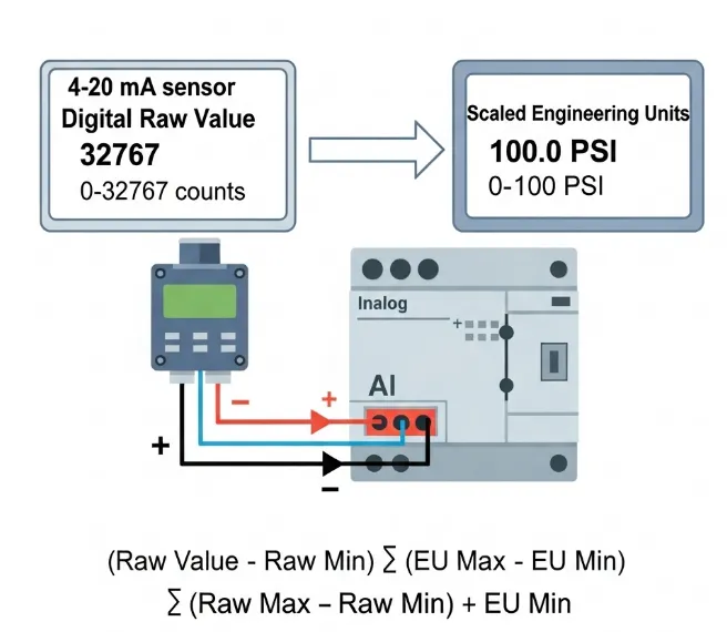
PLC analog input scaling converts raw analog values from sensors or transmitters into engineering units for process control. The standard scaling formula is:
Scaled Value = ((Raw Value – Raw Min) × (EU Max – EU Min) ÷ (Raw Max – Raw Min)) + EU Min. This ensures the PLC interprets the signal correctly, avoiding inaccurate readings.
In this guide, you’ll learn scaling concepts, formula applications, step-by-step programming examples, and best practices for Allen Bradley, Siemens, and other PLC systems. Scaling is essential for accurate measurements in temperature, pressure, flow, and other industrial processes.
Types of Analog Input and Output in PLCs
Analog signals in PLC systems can be categorized by the type of measurement and the signal standard they use. These signals represent continuous values, such as temperature, pressure, or flow, and are crucial for process control.
- Analog Inputs (AI):
- Voltage Inputs: Common ranges include 0–10 V and ±10 V, used for sensors and transducers.
- Current Inputs: Most commonly 4–20 mA, preferred for industrial environments due to noise immunity.
- Resistance Inputs: For devices like RTDs, where resistance changes with temperature.
- Analog Outputs (AO):
- Voltage Outputs: Typically 0–10 V for controlling actuators or drives.
- Current Outputs: Usually 4–20 mA for sending control signals to process devices.
Understanding the type of analog signal is the first step before applying scaling, as the raw input range directly affects the conversion to engineering units.
What is Analog Scaling?
Analog scaling is the process of converting analog input and output to meaningful real engineering units for display and control. This conversion is based on the straight-line equation Y = M × X + b, where:
- M – The scalar (slope), calculated by dividing the engineering unit range by the raw input range (current or voltage).
- X – The raw analog value from the input point.
- b – The offset, used when the ranges do not start at zero.
- Y – The converted engineering unit value to be displayed.
The scalar defines how many engineering units each raw input count represents. Offsets are applied when the engineering units start at a value other than zero, such as with a 4–20 mA current loop.
PLC Analog Scaling Formula
The PLC analog scaling formula is used to convert the raw digital value from an analog input module into meaningful engineering units (°C, PSI, liters, etc.). It is calculated as:

- Raw Value — current ADC count read from the PLC analog input tag (e.g., 9831).
- Raw Min — ADC count when the physical signal is at its minimum (e.g., 4 mA or 0 V). Measured by forcing the input to the minimum signal and reading the tag.
- Raw Max — ADC count when the physical signal is at its maximum (e.g., 20 mA or 10 V). Measured by forcing the input to the maximum signal and reading the tag.
- EU Min — minimum engineering unit (process low), e.g., 0 °C or 0.00 m.
- EU Max — maximum engineering unit (process high), e.g., 200 °C or 5.00 m.
What is Raw Value and How to Calculate It
The Raw Value is the direct digital count that a PLC’s analog input module produces after converting a sensor’s electrical signal (e.g., 4–20 mA or 0–10 V) using its internal ADC (Analog-to-Digital Converter). It is not in engineering units like °C, meters, or PSI — it’s simply the “raw” number from the hardware.
Key Points:
- Comes directly from the analog input tag in the PLC program (before any scaling).
- Depends on:
- PLC analog module resolution (e.g., 12-bit, 13-bit, 15-bit, 16-bit)
- Signal range configured for the module (e.g., 4–20 mA, 0–10 V)
- Measured by monitoring the live PLC input in the programming software.
How to Calculate Raw Value:
- Identify the input signal type and range (e.g., 4–20 mA or 0–10 V).
-
Check the module specifications for its raw count range:
- Example: 4–20 mA on a 16-bit card → Raw Min = 6553, Raw Max = 32767
- Example: 0–10 V on a 15-bit card → Raw Min = 0, Raw Max = 32767
-
Apply the ADC conversion formula if needed:
Raw Value = (Signal Value ÷ Signal Full Scale) × Max Raw Count - Or simply read it directly from the PLC tag (most practical method).
Example:
Sensor output: 12 mA
Module: 16-bit, range = 4–20 mA → Raw Min = 6553, Raw Max = 32767
Step 1: Signal span = 20 mA − 4 mA = 16 mA
Step 2: Raw span = 32767 − 6553 = 26214
Step 3: Position in span = 12 mA − 4 mA = 8 mA
Step 4: Fraction of span = 8 ÷ 16 = 0.5
Step 5: Raw Value = (0.5 × 26214) + 6553
Raw Value = 13107 + 6553 = 19660
So when the sensor outputs 12 mA, the PLC analog input tag will show approximately 19660.
Raw Value is the digital output (ADC count) produced by the PLC analog input module after it converts the sensor's analog signal (e.g. 4–20 mA or 0–10 V). It is not yet in engineering units — it is the raw count that you later map to °C, PSI, meters, etc.
Raw Value (estimation) formula
Raw Value = ((Signal - Signal Min) ÷ (Signal Max - Signal Min)) × (Raw Max - Raw Min) + Raw Min
Where:
- Signal = measured analog value (e.g., mA or V)
- Signal Min = lowest signal for the loop (usually 4 mA or 0 V)
- Signal Max = highest signal for the loop (usually 20 mA or 10 V)
- Raw Min = PLC card count at Signal Min (from module or measured)
- Raw Max = PLC card count at Signal Max (from module or measured)
PLC Analog Scaling Example
Scaling converts a PLC’s raw input counts into real-world engineering units. The general formula is:
Scaled Value = ((Raw − RawMin) ÷ (RawMax − RawMin)) × (EngMax − EngMin) + EngMin
Example 1 — 4–20 mA Sensor: A sensor outputs 12.0 mA, with 4 mA = 3277 and 20 mA = 16384 on the PLC card.
- Signal ratio = (12 − 4) ÷ (20 − 4) = 0.5
- Raw span = 16384 − 3277 = 13107
- Scaled raw = 3277 + (0.5 × 13107) ≈ 9831
Example 2 — Temperature Transmitter: Range: 0–200°C, Raw range: 0–65536. Scalar = 200 ÷ 65536 ≈ 0.0030518°C/count. If Raw = 25000 → Temperature ≈ 76.3°C.
Tip: Always confirm RawMin and RawMax by sending actual min/max signals to the PLC card.
Example Of Scaling in PLC
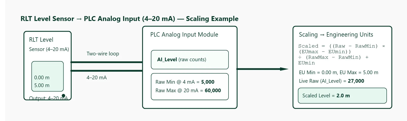
This example uses an RLT series level sensor (4–20 mA output) connected to a PLC analog input module. We will show how to determine raw min/max values, apply the universal scaling formula, and compute a live engineering-unit level reading.
Wiring / connection overview
- RLT level sensor (4–20 mA) → two-wire loop to PLC analog input card (current input).
- PLC analog input tag: AI_Level (monitors the ADC raw count returned by the card).
- PLC scaled tag (calculated): Level_m (engineering units — meters in this example).
Universal scaling formula
Scaled Value = ((Raw Value - Raw Min) × (EU Max - EU Min)) ÷ (Raw Max - Raw Min) + EU Min
How to determine Raw Min and Raw Max (practical)
- Consult the PLC analog module datasheet for expected resolution and factory full-scale counts (e.g., 16-bit = 0–65535 or signed ranges). This gives a starting point.
- Physically force the input to the sensor's low signal (4 mA) and read the PLC tag — record that reading as Raw Min.
- Physically force the input to the high signal (20 mA) and read the PLC tag — record that reading as Raw Max.
- If you cannot force current, use the documented mapping in the module manual or use a calibrated transmitter and read the tag at known process points (e.g., empty/full tank).
Example (worked numeric)
Assumptions / system specifics:
- Sensor: RLT level transmitter, output 4–20 mA → corresponds to 0.00 m to 5.00 m (EU Min = 0 m, EU Max = 5 m).
- PLC analog input module measured values (found by applying 4 mA and 20 mA and reading the input tag):
- Raw Min (4 mA) = 5,000
- Raw Max (20 mA) = 60,000
- Live raw reading (AI_Level) = 27,000 (example)
Apply the formula:
Level_m = ((RawValue - RawMin) × (EUmax - EUmin)) ÷ (RawMax - RawMin) + EUmin

Level_m = ((27,000 - 5,000) × (5.0 - 0.0)) ÷ (60,000 - 5,000) + 0.0
        = (22,000 × 5.0) ÷ 55,000
        = 110,000 ÷ 55,000
        = 2.0 m
So a raw reading of 27,000 maps to 2.0 m level.
Notes & best practices
- Always measure Raw Min/Max from the actual PLC card by forcing 4 mA and 20 mA (or using a known, calibrated source). Do not assume module counts without verifying.
- If the PLC card reports negative or signed raw ranges, convert to the unsigned mapping used by your process or use the card's recommended mapping formula. The linear formula above still applies once RawMin/RawMax are known.
- Apply filtering, smoothing, or deadband in the PLC if the raw signal is noisy. Do scaling after any required filtering so the displayed EU value is stable.
- Document the calibration values (RawMin/RawMax and the date) in your program comments or tag descriptions for future maintenance.