Induction Motor Starter Types and Applications – Motor Starter: Function, Types, Diagram, and Working
Published on July 7, 2024 | Category: introductionShare this Page:
Induction motors are widely used in industrial, commercial, and residential applications due to their simple construction, low cost, and rugged performance. However, starting an induction motor directly on full line voltage can cause high inrush current, voltage dips, mechanical stress, and damage to connected equipment. To overcome these challenges, motor starters are used to limit starting current, control voltage application, and ensure safe acceleration of the motor.
This page provides a comprehensive overview of induction motor starter types and their applications. It explains the function of motor starters, their working principles, advantages, wiring diagrams, and typical use cases. You’ll learn about common starter types such as Direct-On-Line (DOL) starters, Star-Delta starters, Autotransformer starters, Soft Starters, and Variable Frequency Drives (VFDs), each suited for specific motor sizes and load conditions.
Whether you are a maintenance technician, electrical engineer, or student preparing for interviews, understanding the working and selection of motor starters is critical in motor control and automation systems. The choice of starter depends on several factors like motor rating, load torque, voltage class, and protection requirements. Diagrams and real-world examples are included to help visualize connections and operation.
From reducing starting current to enabling smooth acceleration and improved efficiency, this guide covers everything you need to know about induction motor starters. Explore how to choose the right starter for different applications in HVAC, water pumps, conveyors, compressors, fans, and more.
What is a Motor Starter?
A motor starter is an electrical device used to safely start and stop an electric motor while also providing protection against high starting current, known as inrush current. When an electric motor is first powered on, it draws a large surge of current — typically 5 to 8 times its full-load current — because there is no back EMF (Electromotive Force) to oppose the applied voltage. This sudden surge is called inrush current.
To limit this high inrush current, a starter is connected in series with the motor. The starter adds external resistance or controls voltage at the beginning, and then reduces or removes it gradually as the motor gains speed and develops its own back EMF.
Motor starters are essential because they help limit this inrush current to a safe level during startup. Without a starter, this high current can cause voltage drops, damage to motor windings, insulation failure, tripping of circuit breakers, or even complete motor burnout. Starters achieve current reduction either by limiting the applied voltage, introducing series resistance, or controlling voltage and frequency electronically.
There are several types of motor starters used depending on the motor size and application, including:
- Direct-On-Line (DOL) Starter – Connects the motor directly to full voltage; used only for small motors due to high inrush current.
- Star-Delta Starter – Starts the motor in star connection (lower voltage), then switches to delta (full voltage) to reduce initial current.
- Soft Starter – Gradually increases voltage using thyristors or SCRs to limit inrush current smoothly.
- Variable Frequency Drive (VFD) – Controls both voltage and frequency during startup for the most efficient and precise current control.
Example: A 7.5 kW induction motor used for pumping water in an industrial plant, if started directly, may draw over 300 A of inrush current. By using a Star-Delta starter, the starting current is reduced to approximately one-third, protecting the motor and preventing voltage sag in the network.
Why Do We Use a Motor Starter? Why Can't We Start a Motor Directly?
In large 3-phase induction motors, the stator resistance is very low. If such motors are connected directly to the full supply voltage, they draw an extremely high inrush current — often 6 to 8 times the rated full-load current. This sudden current surge can result in:
- Significant voltage drops in the entire power system
- Damage to windings and overheating of insulation
- Mechanical stress on the shaft, bearings, and couplings
- Unwanted tripping of fuses, circuit breakers, or relays
- Heavy sparking in DC motors due to brush contact
To prevent these effects, a motor starter is used. It limits the initial voltage or current applied to the motor during startup, ensuring smooth acceleration, reducing mechanical shock, and protecting both the motor and connected load. Many starters also include features like overload and phase failure protection.
Role of Back EMF in Starting Current
One of the main reasons for high starting current is the absence of back EMF (Electromotive Force) when the motor is not yet rotating. Back EMF is generated only when the rotor spins, and it acts like a natural opposition to the supply voltage.
The back EMF (Eb) is calculated as:
Eb = (P × Φ × Z × N) / (60 × A)
Where: P = Number of poles, Φ = Magnetic flux per pole, Z = Total number of armature conductors, N = Rotor speed (in RPM), A = Number of parallel paths in winding
At startup, the rotor is stationary (N = 0), so Eb = 0. The only opposition to the applied voltage is the motor’s internal resistance (Ra), which is very low. This results in very high armature current:
Ia = (V - Eb) / Ra ⇒ Ia = V / Ra (since Eb = 0 at start)
For example, if the supply voltage is 240 V and armature resistance is 0.8 Ω:
Ia = 240 ÷ 0.8 = 300 A
This high current (often 10 to 15 times the rated value) can burn the windings, damage circuit components, and reduce motor lifespan.
When a Starter May Not Be Needed
In small motors (typically below 1 HP), the internal armature resistance is relatively high. This naturally limits the starting current to a safe level. Therefore, such motors can be started directly without a starter in most cases.
Conclusion
We use a motor starter primarily to control inrush current and protect the motor during startup. The starter plays a key role in managing the lack of back EMF at zero speed, ensuring safe and reliable motor operation. For large motors, using the right starter is not optional — it's essential for safety, performance, and equipment longevity.
What is Inrush Current and Why Does It Happen?
Inrush current is the maximum, instantaneous input current drawn by an electrical device when it is first turned on. In motors, especially induction motors and transformers, this current is significantly higher than the normal operating current and occurs during the initial energization phase.
When an electric motor starts, the rotor is stationary (speed = 0), and there is no back EMF generated. Back EMF (Electromotive Force) is the voltage that opposes the applied voltage and is produced only when the motor is rotating. In the absence of back EMF, the only opposition to the current flow is the motor’s internal resistance, which is typically very low.
As a result, using Ohm’s Law:
I = V / R
Where:
V = Supply Voltage,
R = Motor winding resistance (very low)
The current drawn (I) becomes extremely high during the first few milliseconds after startup — often 6 to 8 times the full-load current. This surge is known as inrush current.
Example:
Consider a 3-phase induction motor connected to a 415V supply with a winding resistance of 1.2 Ω. At startup:
I = V / R = 415 / 1.2 ≈ 345.8 A
This current is far beyond the motor’s rated full-load current and can cause voltage dips, tripping of circuit breakers, and damage to the winding insulation if not controlled.
Why Does Inrush Current Occur?
- The motor is not yet rotating, so there is no back EMF to oppose the supply voltage.
- Stator windings offer very low resistance to current flow.
- High magnetic flux is needed initially to overcome inertia and start the rotor motion.
How to Control Inrush Current:
- Use a motor starter (DOL, star-delta, soft starter)
- Apply reduced voltage starting techniques
- Use a Variable Frequency Drive (VFD) for smooth ramp-up
Inrush current is a normal but critical phenomenon in motor operation, and must be properly managed to ensure system safety and motor longevity.
What Happens If We Don’t Connect a Starter with a Motor?
If a motor—especially a large AC or DC motor—is started without a starter, it will draw a very high inrush current at the moment of energization. This current can be 5 to 10 times higher than the motor’s full-load current, which poses serious risks to both the motor and the electrical system.
Consequences of Not Using a Starter:
- Overheating of Windings: The excessive current causes rapid temperature rise in the stator or armature windings, damaging insulation and shortening motor life.
- Voltage Drop in Power System: High current draw can cause voltage dips across the entire electrical network, affecting other connected equipment.
- Tripping of Circuit Breakers: Protective devices may interpret the inrush as a fault, leading to unnecessary shutdowns.
- Mechanical Stress: Sudden torque can damage couplings, gearboxes, belts, and connected loads like pumps or fans.
- No Controlled Acceleration: Without a starter, the motor starts instantly at full torque, increasing wear and tear on both the motor and mechanical systems.
Example:
Consider a 10 HP induction motor directly connected to a 415V supply. If the motor's full-load current is 15 A, it may draw 90–100 A at startup without a starter. This can overheat the windings and damage sensitive electronic components in the system.
Conclusion:
Connecting a starter is essential for large motors to limit the starting current, protect equipment, and ensure smooth operation. Small motors under 1 HP may not require starters, but for industrial motors, a suitable starter is mandatory for safety, performance, and regulatory compliance.
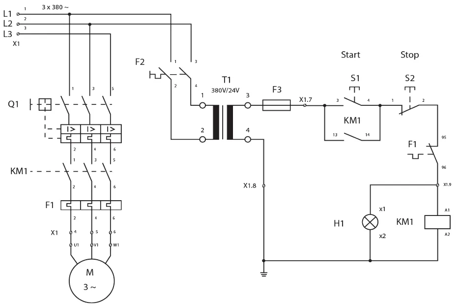
What is a DOL (Direct-On-Line) Starter?
A Direct-On-Line (DOL) starter is the simplest and most widely used method for starting small AC induction motors. It connects the motor terminals directly to the full line voltage, allowing the motor to start immediately at its rated voltage and frequency.
The DOL starter typically consists of a contactor, overload relay, and a control mechanism such as a push button, selector switch, limit switch, or float switch. When the start button is pressed, it energizes the contactor coil, closing the main contacts and supplying power directly to the motor. The motor then starts and runs at full speed.
To stop the motor, a stop button is used to de-energize the contactor coil, which opens the main contacts and cuts off power to the motor. For protection against overcurrent, the control circuit includes a normally closed auxiliary contact of the overload relay. If an overload occurs, the relay trips, opening the auxiliary contact and interrupting the coil circuit, which safely disconnects the motor from the supply.
Applications of DOL Starter
- Water pumps
- Conveyor belts
- Small compressors
- Mixers and grinders
- Small fans and blowers
- Lathe and milling machines (below 5 HP)
Where is DOL Starter Used?
DOL starters are used in applications where:
- The motor power is low (typically below 5 HP or 3.7 kW).
- High starting torque is not required.
- The power supply system can handle high inrush currents without voltage dips.
Advantages of DOL Starter
- Simple construction and easy to operate
- Low cost and minimal components
- Quick and full-voltage starting
- Provides overload protection through thermal relay
Limitations of DOL Starter
- High inrush current during starting — 6 to 8 times the full-load current
- Causes mechanical stress on motor and load
- May lead to voltage drop in weak power systems
- Not suitable for motors above 5 HP or for sensitive loads
Conclusion
DOL starters are best suited for small, robust motors in systems that can tolerate high starting current. For larger motors or loads requiring smooth acceleration, alternative starters like Star-Delta, Soft Starter, or VFD should be used.
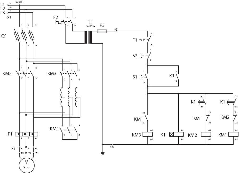
What is a Star-Delta Starter?
A Star-Delta Starter is a widely used electrical starter designed to reduce the inrush current and starting torque of three-phase induction motors. It works by initially connecting the motor windings in a star (Y) configuration during startup and then automatically switching to a delta (Δ) configuration once the motor reaches a certain speed.
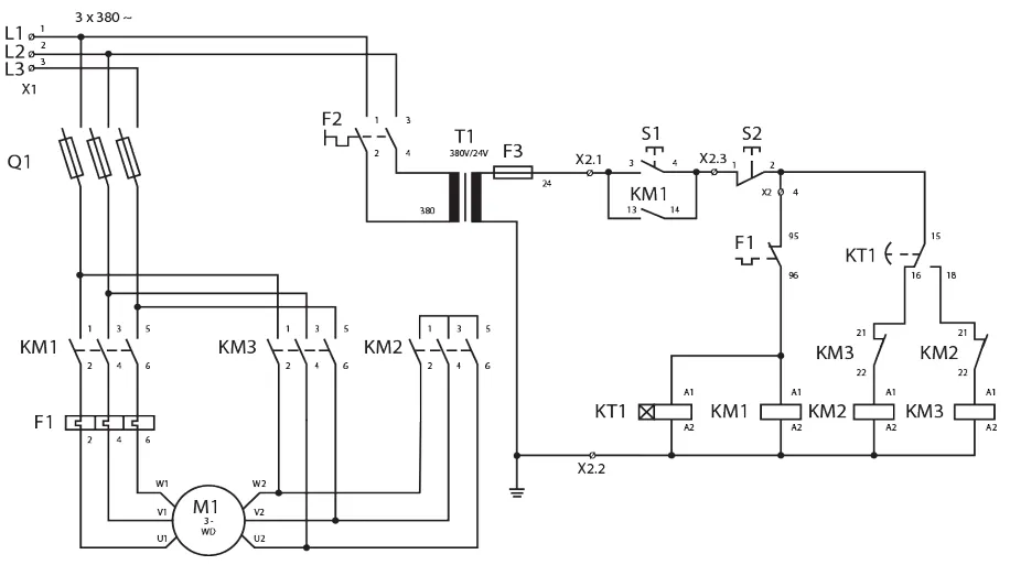
In the star configuration, the phase voltage applied to each motor winding is reduced to approximately 58% of the line voltage. This causes the starting current to drop to about one-third of what would be drawn in a Direct-On-Line (DOL) start, making it an effective method to minimize electrical and mechanical stress during startup.
After a preset time delay (configured using a timer or control relay), the starter automatically switches the winding connections from star to delta. In delta mode, the motor receives full line voltage, enabling it to operate at its rated power and deliver full torque.
The Star-Delta starter is ideal for large motors with low load torque at startup and is commonly used in fans, pumps, compressors, and conveyors. It is not suitable for applications requiring high starting torque, as the initial torque in star configuration is significantly reduced.
Applications of Star-Delta Starter
- Large industrial motors (typically above 5 HP)
- Pumps and compressors
- Conveyor belts with heavy startup loads
- Blowers and crushers
- HVAC systems with fans and chillers
Where is Star-Delta Starter Used?
- When the motor load allows for reduced starting torque
- For motors designed for delta connection at full load
- When the supply network cannot tolerate high inrush current
Advantages of Star-Delta Starter
- Reduces starting current to approximately 1/3 of DOL
- Minimizes mechanical stress on motor shaft and load
- Cost-effective for motors >5 HP
Limitations of Star-Delta Starter
- Only suitable for motors with delta-rated windings
- Sudden transition from star to delta can cause torque dips
- Not suitable for high-torque loads at startup
Conclusion
The Star-Delta Starter is a widely used method for safely starting medium to large motors by lowering inrush current and mechanical stress. It is preferred in industrial applications where torque demand at startup is low to moderate, and energy systems require current-limiting solutions.
What is a Soft Starter?
A Soft Starter is a solid-state device used to gradually ramp up the voltage applied to an AC motor during startup. This smooth acceleration significantly reduces inrush current, starting torque, and mechanical stress on the motor and connected load.
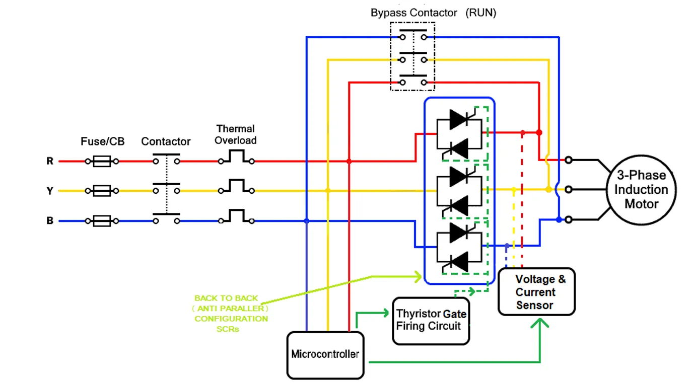
Soft starters typically use thyristors (SCRs) to control the voltage applied to the motor in the initial few seconds. Once the motor reaches a certain speed, the starter bypasses the SCRs and allows full voltage to the motor. Many soft starters include built-in features such as current limiters, torque control, programmable ramp times, and motor protection.
Applications of Soft Starter
- Water pumps (to prevent water hammering)
- HVAC fans and compressors
- Conveyors and elevators
- Mixers and centrifuges
- Industrial blowers
Advantages of Soft Starter
- Reduces inrush current and mechanical shock
- Extends life of motor and driven equipment
- Prevents belt slippage and pressure surges
- Smaller and lighter than Star-Delta starters
Limitations of Soft Starter
- Not suitable for applications requiring speed control after startup
- More expensive than DOL or Star-Delta starters
- Still allows higher current than a VFD under certain conditions
Conclusion
Soft Starters are ideal for applications where smooth motor acceleration is essential, especially where sudden torque changes can damage mechanical systems. While not offering speed control like VFDs, they are cost-effective and energy-efficient for many industrial processes.
What is a VFD (Variable Frequency Drive)?
A Variable Frequency Drive (VFD) is an advanced motor control device that varies the frequency and voltage supplied to an AC motor. This allows the motor to operate at variable speeds, reduce inrush current, and improve overall energy efficiency.
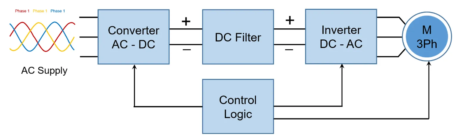
VFDs use rectifiers and inverters to convert fixed AC input into variable frequency AC output. Unlike other starters, VFDs can start, stop, accelerate, decelerate, and maintain precise speed control throughout the motor's operation. They also include safety features such as short circuit, over-voltage, and thermal protection.
Applications of VFD
- Variable-speed pumps and fans
- Conveyors with dynamic speed requirements
- Extruders, compressors, and machine tools
- Textile and printing machinery
- Elevators and escalators
Advantages of VFD
- Precise motor speed and torque control
- Greatly reduces inrush current and mechanical wear
- Energy savings in variable load systems
- Advanced diagnostics and programmable logic
Limitations of VFD
- Higher initial cost compared to other starters
- Requires proper filtering to avoid harmonics and EMI
- Complex configuration and maintenance
Conclusion
VFDs are the most flexible and energy-efficient motor starters available. They not only minimize inrush current and protect the motor but also provide speed control, making them ideal for modern automation and energy-saving systems.
What is an Autotransformer Starter?
An Autotransformer Starter is a type of reduced voltage starter used to limit the starting current and torque of large three-phase induction motors. It operates by initially applying a reduced voltage to the motor through an autotransformer and then switching to full line voltage once the motor reaches a certain speed.
Unlike Star-Delta starters that reduce voltage by altering motor winding configuration, the autotransformer starter uses tapped windings to deliver 50%, 65%, or 80% of the line voltage during startup. This significantly reduces inrush current and mechanical shock, making it suitable for motors that require high torque at startup.
The autotransformer is typically connected in a star configuration, and the three tapped secondary coils are connected to the motor phases. When the motor is started, it receives reduced voltage from the selected transformer tap. After a brief period (usually 5–10 seconds), a timer or current sensing relay triggers a contactor that bypasses the autotransformer and connects the motor directly to the full line voltage.
Working Principle
1. The autotransformer initially supplies reduced voltage to the motor through tapped windings.
2. This reduces the starting current and torque.
3. A timer or relay transitions the motor to full voltage after acceleration.
4. The transition is smooth and protects both the motor and supply network from high starting stress.
Applications of Autotransformer Starter
- Large compressors and blowers
- Industrial pumps and cranes
- Fans, crushers, and rolling mills
- Heavy machinery requiring high starting torque
Advantages
- Reduces starting current to 25–80% of DOL levels
- Provides higher starting torque than Star-Delta starters
- Adjustable voltage taps offer flexible startup control
- Minimizes mechanical and electrical stress on motor
Limitations
- More complex and expensive than DOL or Star-Delta starters
- Bulky due to transformer size
- Not economical for motors below 10 HP
Conclusion
The Autotransformer Starter is ideal for large industrial motors that require high torque at startup while keeping the inrush current within limits. It offers greater flexibility and smoother transitions compared to Star-Delta starters and is widely used in heavy-duty applications demanding performance and protection.
What is a Rotor Resistance (Slip Ring) Motor Starter?
A Rotor Resistance Starter, also known as a Slip Ring Motor Starter, is used specifically with slip ring induction motors. It introduces external resistances into the rotor circuit during startup to improve starting torque and limit the inrush current, making it ideal for heavy-duty industrial applications.
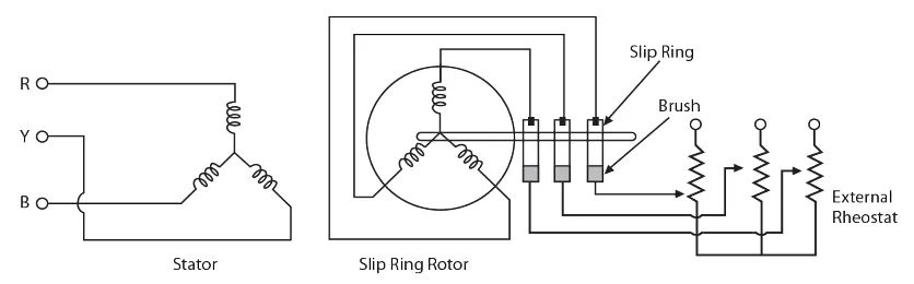
In this starter, three external resistors are connected in series with the rotor windings via slip rings and brushes. These resistors reduce rotor current and increase the torque produced during startup. As the motor accelerates, the resistors are gradually cut out in steps (either manually or automatically), and once full speed is achieved, the rotor windings are short-circuited for normal operation.
Working Principle
When the motor starts:
- External resistors are inserted into the rotor circuit using slip rings.
- This increases rotor resistance, improving the starting power factor and torque.
- As speed builds up, resistors are progressively removed until the rotor runs with minimal resistance.
Applications of Rotor Resistance Starter
- Hoists, cranes, and elevators
- Rolling mills and crushers
- Heavy conveyor systems
- Fans with high-inertia loads
- Machinery requiring frequent starts and stops
Advantages
- High starting torque with smooth acceleration
- Reduced inrush current compared to DOL
- Simple and cost-effective torque control
- Flexibility through adjustable rotor resistance values
Limitations
- Requires regular maintenance of slip rings and brushes
- Bulky external resistor banks increase space requirements
- Not ideal for very high-speed or precise applications
Conclusion
The Rotor Resistance Starter is a reliable and efficient method for starting slip ring induction motors, especially in applications where high torque and controlled acceleration are essential. While it involves more maintenance than other starters due to mechanical components like brushes and slip rings, its benefits make it a preferred choice for demanding industrial environments.
What is a Stator Resistance Starter?
A Stator Resistance Starter is a type of reduced voltage starter used for starting squirrel cage induction motors. It operates by connecting variable resistors in series with each phase of the stator winding. These resistors reduce the voltage applied to the motor during startup, thereby limiting the inrush current and reducing the initial torque.
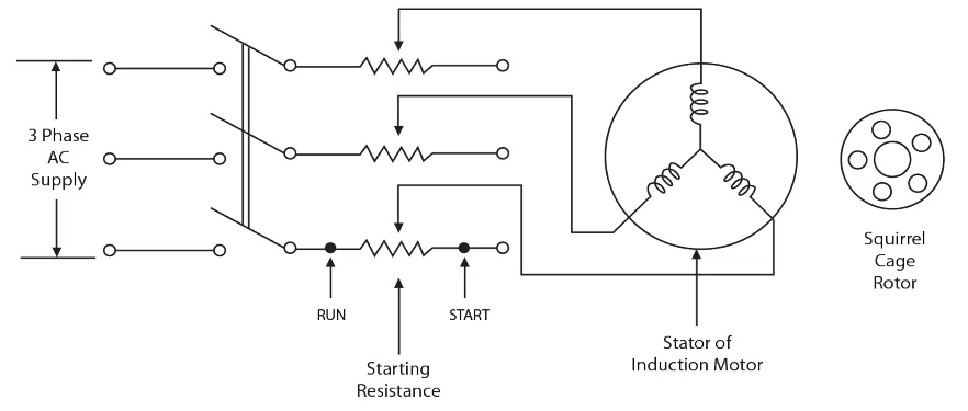
During startup, the resistors cause a voltage drop across each phase, resulting in a lower voltage being applied to the motor terminals. This decreases the starting current while maintaining moderate torque. As the motor speed increases, the resistors are gradually bypassed (either manually or automatically), and full line voltage is applied for normal operation.
Working Principle
- Three resistors are connected in series with each stator phase during motor startup.
- These resistors reduce the voltage across motor terminals, limiting the starting current.
- As the motor picks up speed, the resistors are progressively shorted out.
- Eventually, full voltage is applied, and the motor runs under normal conditions.
Applications
- Fans and blowers with low starting torque requirements
- Pumps where gradual acceleration is preferred
- Textile machinery
- Industrial machines with moderate torque demands at startup
Advantages
- Simple design and easy to implement
- Reduces inrush current and protects the motor
- Lower mechanical stress on load during startup
- Cost-effective for low and medium power applications
Limitations
- Starting torque is reduced along with voltage
- Energy loss occurs due to heat dissipation in resistors
- Not suitable for high torque startup applications
- Requires additional components like bypass contactors
The Stator Resistance Starter is best suited for applications where energy efficiency is not critical, and where moderate starting torque is acceptable. It provides a basic yet reliable solution to control inrush current in squirrel cage induction motors.
Comparison of Motor Starter Types
| Starter Type | Startup Current | Speed Control | Torque Control | Applications | Motor Size | Cost |
|---|---|---|---|---|---|---|
| DOL Starter | 6–8 × Full Load Current | No | No | Small pumps, fans, grinders | < 5 HP | Low |
| Star-Delta Starter | 2–3 × Full Load Current | No | Partial | Compressors, blowers, conveyors | 5 HP – 100 HP | Medium |
| Soft Starter | Controlled (Adjustable) | No (Startup only) | Yes | Pumps, mixers, HVAC systems | Any | Medium–High |
| VFD | Lowest (Fully controlled) | Yes | Yes | Variable-speed loads, fans, extruders | Any | High |
Quick Summary of Starter Types
- DOL Starter: Simple and economical, best for small motors under 5 HP. High inrush current, no speed control.
- Star-Delta Starter: Reduces starting current using star-to-delta transition. Common in medium-sized industrial motors.
- Soft Starter: Uses SCRs to ramp voltage gradually. Reduces torque shock and increases system life.
- VFD: Most advanced. Offers full-speed and torque control. Used where energy efficiency and precision control are critical.
Which Starter Should You Choose?
The right motor starter depends on your application:
- Use DOL for small motors in simple, non-critical applications.
- Use Star-Delta where reduced starting current is needed, but not precision control.
- Use Soft Starter for smoother startups and longer motor life.
- Use VFD when you need full speed control, energy savings, and intelligent protection.
Fundamental Functions of Motor Starters
Motor starters are essential devices that not only initiate motor operation but also ensure safe and controlled performance under various load and fault conditions. The following are the core functions performed by a motor starter:
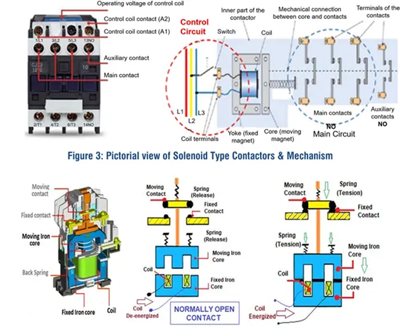
1. Control
The control function is primarily managed by the contactor, a key component of the motor starter. It controls the opening and closing of the power circuit by energizing or de-energizing an electromagnetic coil. When energized, this coil closes the main contacts (poles), allowing current to flow to the motor. The coil operates on a nominal control voltage, which can be either AC or DC, depending on the application.
2. Short-Circuit Protection
In industrial environments, motors often operate at very high currents. In the event of a short-circuit fault, fault current levels can exceed 100,000 amperes, which may cause catastrophic equipment damage. To prevent this, short-circuit protection is implemented using fuses or circuit breakers. These protective devices disconnect the power supply instantly to prevent further damage and ensure operator safety.
3. Overload Protection
When a motor draws more current than its rated capacity, an overload condition occurs. This can result in excessive heating and potentially lead to motor failure. Overload relays (electromechanical or electronic) are used in combination with contactors to detect this condition. Once detected, the relay opens its auxiliary contacts and interrupts the circuit, protecting the motor from overheating or burning out.
4. Disconnecting and Breaking
For safe maintenance and servicing, it is crucial to completely disconnect the motor from the power source. This prevents accidental restarts and ensures safety during electrical or mechanical work. This function is performed by a disconnect switch or circuit breaker, either integrated into a Combination Motor Controller or installed externally. It isolates the motor from the power circuit and ensures a complete break from the supply.