What is a Motor Control Center (MCC)? – Definition, Components, and Industrial Applications
Published on July 14, 2024 | Category: BasicShare this Page:
A Motor Control Center (MCC) is a centralized system made up of one or more enclosed units designed to efficiently control, monitor, and protect electric motors. These units typically include essential motor control equipment such as circuit breakers, contactors, overload relays, and auxiliary devices. MCCs are commonly installed in commercial buildings, factories, and industrial plants where multiple motors are used across different processes.
The concept of MCCs was first introduced in the 1950s, particularly in the automotive industry, to streamline the operation of numerous motors used in manufacturing and assembly lines. Over time, MCCs have evolved into a core part of industrial automation, offering modularity, space-saving layouts, and centralized control for better operational efficiency.
Today, MCCs are widely adopted in sectors such as oil and gas, water treatment, power generation, and HVAC systems. They provide a reliable solution for managing complex motor operations from a single location, enhancing not only system safety but also ease of maintenance and troubleshooting.
This page explores the fundamentals of Motor Control Centers — from how they work and what they consist of, to their different types and where they are most commonly applied. Whether you're new to industrial electrical systems or looking to expand your technical knowledge, this guide will help you gain a clear understanding of MCCs and their vital role in modern electrical infrastructure.
What is a Motor Control Center?
Motor Control Centers (MCCs) provide the most effective solution for grouping motor control devices and associated power distribution equipment. They offer a compact, economical, and organized way to manage electrical motor control, automation, and distribution within a facility.
An MCC typically consists of totally enclosed, dead-front, free-standing metal structures that are bolted together. These sections are designed to house motor control units and include a common bus bar for power distribution, wire troughs, and entry areas for both incoming and outgoing load/control wiring.
The control units can contain a variety of components, including combination motor starters, branch feeder devices, AC drives, soft starters, or lighting panelboards. Each unit is mounted in an isolated compartment with its own access door, ensuring safety and ease of maintenance.
Standard dimensions for MCC sections are typically 20 inches wide (including a 4-inch vertical wireway), 90 inches high (plus 1.5-inch base channel and 3-inch removable top lifting channel), and 15 or 20 inches deep. Larger enclosures may be used to accommodate larger control equipment or customer-installed devices.

How a Motor Control Center (MCC) Operates
A Motor Control Center (MCC) is a centralized system designed to manage, protect, and control multiple electric motors in an industrial or commercial facility. The following section explains how power flows through the system and how the MCC fits into the overall distribution architecture.
Understanding MCC Operation with Reference Diagram
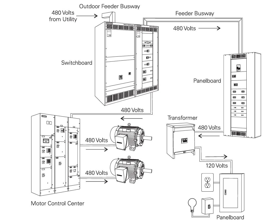
The image below represents the typical power flow from the utility to the final motor loads via the MCC and associated components. Here's a simplified explanation of each stage in the process:
- Power Source (480V from Utility): The system begins with a utility power supply delivering 480 volts, which enters the facility through an outdoor feeder busway.
- Switchboard: The switchboard acts as the primary distribution panel that receives power from the utility and provides protection, control, and metering functionalities. It distributes the 480V to various parts of the system.
- Feeder Busway: This component transfers 480V power from the switchboard to downstream equipment like panelboards and MCCs. It helps distribute power across large distances efficiently.
- Panelboard: The panelboard splits the electrical power into branch circuits and may feed equipment like transformers or smaller loads directly.
- Transformer: For devices that require lower voltages (such as 120V outlets or control circuits), the transformer steps down the 480V to 120V.
- 120V Panelboard: This panelboard distributes the 120V supply to common devices like outlets, lighting systems, and small equipment.
-
Motor Control Center (MCC):
The MCC receives 480V from the switchboard or panelboard and supplies it to various motors. Inside the MCC, each motor control unit typically includes:
- Switch-fuse units (SFUs)
- Overload relays
- Contactors
- Start/Stop buttons and protection relays
- Motors: Finally, the controlled and protected 480V power is delivered to connected motors to run various processes and equipment.
Conclusion
This structured approach enables centralized control, enhanced protection, and easier maintenance of electric motors across an industrial facility. The MCC forms the operational heart of the motor system, ensuring safe and efficient performance.
Basic Components of a Motor Control Center (MCC) and Its Features
NEMA Definition and Standards
According to NEMA ICS 2-322, a Motor Control Center (MCC) is defined as: “A floor-mounted assembly of one or more enclosed vertical sections having a horizontal common power bus and principally containing combination motor control units. These units are mounted one above the other in the vertical sections.”
MCCs must also comply with standards set by organizations such as the National Electrical Code (NEC) for bus spacing, grounding, and safety. NEMA also provides guidelines for busbar phase arrangements, enclosure types, and component safety ratings.
Main Components of MCC
1. Power Supply System
- Main Power Source: Supplies the incoming voltage to the MCC, typically 3-phase AC.
- Power Supply Units: Convert or step-down voltage for control circuits (e.g., 24V DC for PLCs).
2. Busbar System
- Horizontal Bus: Distributes power across the MCC to each vertical section.
- Vertical Bus: Supplies power to each individual motor control unit in a section.
- Bus Support and Bracing: Ensures the busbars are firmly held in place and protected from mechanical or electrical damage.
3. Motor Control Units
- Contactors: Electromagnetic switches used to start/stop motors remotely.
- Overload Relays: Protect motors from prolonged overcurrent situations.
- Soft Starters: Gradually increase motor voltage to reduce mechanical stress during startup.
- VFDs (Variable Frequency Drives): Control the speed and torque of AC motors for energy efficiency.
4. Control Units
- PLCs (Programmable Logic Controllers): Used for automation and logical control of motors based on inputs and outputs.
- Timers & Relays: Used for sequencing, delay functions, and interlocking between devices.
5. Pilot Devices
- Push Buttons: Start/stop controls for motor operation (manual).
- Selector Switches: Used to select between operating modes like Manual/Auto, Forward/Reverse, etc.
- Pilot Lights: Provide visual indication of motor status (e.g., running, fault, off).
- Emergency Stop Switches: Safety devices used to immediately shut down power in an emergency.
6. Protection Devices
- Fuses: Provide short-circuit protection and must be replaced after tripping.
- Circuit Breakers: Offer manual and automatic protection from overload and short circuits. Can be reset after a fault.
- Fusible Disconnect Switches: Combine manual disconnection with fuse protection.
7. Cabling and Wiring System
- Power Cables: Carry the main power from busbars to motors and devices.
- Control Cables: Used for signal wiring between control units (PLCs, push buttons) and output devices.
- Wire Troughs and Conduit: Organized paths for routing cables safely within the MCC panel.
8. Digital Monitoring & Metering
- Digital Meters: Monitor current, voltage, power factor, and energy usage in real time.
- Communication Ports: Allow connection to SCADA or industrial monitoring systems via protocols like Modbus, Profibus, or Ethernet.
9. Communication
- Industrial Communication Systems: MCCs often include communication modules or ports that enable integration with plant-wide systems such as SCADA, DCS, or Building Management Systems (BMS).
- Protocols: Commonly supported protocols include Modbus, Profibus, Profinet, Ethernet/IP, and DeviceNet, allowing real-time data exchange for diagnostics, control, and remote monitoring.
- Benefits: Communication capabilities enhance predictive maintenance, fault detection, energy usage tracking, and remote command execution — all of which contribute to smarter and more efficient operations.
Additional Features
- Modular Construction: MCC sections can be added or removed as needed.
- Front & Rear Access: Some MCCs allow for dual access for easier wiring and maintenance.
- Shipping Splits: Large MCCs are split into sections (usually 20” wide) for easier transport and assembled on site.
Conclusion
A Motor Control Center integrates all necessary motor control and protection devices in a centralized, safe, and efficient manner. From power distribution via busbars to intelligent automation using PLCs and VFDs, MCCs are a backbone of modern industrial electrical infrastructure.

Why We Use a Motor Control Center (MCC)
Motor Control Centers (MCCs) are widely used in industrial and commercial facilities because they offer a centralized, efficient, and safe way to manage multiple electric motors. Below are some key advantages of using an MCC:
- Centralized Control: Multiple motors can be operated from one location, streamlining operations and simplifying troubleshooting and monitoring.
- Faster and Easier Installation: MCCs are designed to be modular and pre-wired, reducing installation time and effort compared to individual starters.
- Space Saving: The vertical arrangement and compact design of MCCs require less floor space, making them ideal for large facilities with limited room.
- Neat and Organized Layout: MCCs provide a clean and professional appearance, with well-organized wiring and components that enhance system reliability.
- Easy Integration of Additional Components: Components such as service entrance switches, transformers, and load centers can be easily added to an MCC panel.
- Scalability and Flexibility: MCCs allow for future expansion by adding new starters or increasing the capacity of existing units without major rewiring.
- Improved Safety: Operators interact with control units rather than directly with motors, reducing the risk of electrical hazards and improving workplace safety.
- Enhanced Energy Efficiency: With the integration of Variable Frequency Drives (VFDs) and soft starters, MCCs can optimize motor performance, saving energy during low-demand periods.
- Simplified Maintenance: Each motor control unit is housed in an isolated, accessible compartment, allowing for quick diagnostics and maintenance without affecting the rest of the system.
Installation and Maintenance of Motor Control Centers (MCCs)
Installation Guidelines
- Site Preparation: Ensure a clean, dry, and well-ventilated location with proper floor leveling and foundation support.
- Grounding: Proper earthing is essential for safety and to avoid electrical noise in control circuits.
- Cable Management: Use wire troughs and conduit for organizing power and control cables to prevent tangling and mechanical stress.
- Panel Alignment: When installing multiple sections, align panels properly and securely connect horizontal busbars.
- Environmental Considerations: Use weatherproof or dust-proof enclosures in outdoor or harsh environments (NEMA-rated enclosures).
- Initial Testing: Verify voltage, insulation resistance, bus connections, and ensure proper functioning of control and protection devices before energizing the MCC.
Maintenance Best Practices
- Periodic Inspection: Regularly inspect for loose connections, discoloration, unusual noises, or overheating in contactors, relays, and busbars.
- Cleaning: Remove dust, debris, and corrosion from internal components to avoid tracking or faults.
- Thermal Scanning: Use IR thermography to detect hot spots and prevent potential failures due to overheating.
- Component Testing: Check overload relays, circuit breakers, contactors, PLC modules, and pilot devices for correct operation.
- Firmware & Software Updates: Keep PLCs and digital monitoring systems updated to the latest versions for improved functionality and security.
- Documentation: Maintain up-to-date wiring diagrams, test reports, and maintenance logs for troubleshooting and future expansion.
Proper installation and regular maintenance ensure the safe, reliable, and long-term operation of Motor Control Centers. A well-maintained MCC minimizes downtime, reduces repair costs, and increases overall plant productivity.
🔧 Causes of MCC Failures – Summary
Motor Control Centers (MCCs) are vital components in industrial operations, but they can experience failure due to a range of electrical, mechanical, and environmental issues. Below are the most common causes, organized for clarity and understanding.
1. Electrical Overload
- Occurs when the motor draws more current than its rated capacity.
- Overload protection devices may fail or not match the motor's load.
- Results in overheating, insulation damage, and tripping of components.
2. Aging and Wear of Components
- Prolonged exposure to heat, dust, and mechanical movement causes deterioration.
- Older MCCs are more prone to failure without proper maintenance.
- Components like relays, contactors, and breakers degrade over time.
3. Mechanical Failures in Connected Equipment
- Motor issues such as bearing failure, shaft misalignment, or unbalanced loads.
- Excessive vibration stresses MCC components, causing loose wiring or terminal damage.
4. Faulty Installation & Loose Connections
- Improper wiring, grounding, or ignoring installation instructions can lead to failure.
- Loose connections create arcing, heat buildup, and potential short circuits.
5. Environmental Factors
- High humidity: Can cause condensation and internal short-circuits.
- Dust and debris: May clog vents and increase heat levels.
- Corrosive gases: Can degrade metal parts and terminals.
- Excess heat: Accelerates wear and damages insulation.
Preventive Tip
Regular inspections, proper installation, scheduled maintenance, and using weather-protected enclosures (e.g., NEMA-rated) can significantly reduce MCC failures and increase operational reliability.