What is an Induction Motor? Working, Types, and Industrial Uses
Published on July 4, 2024 | Category: introductionShare this Page:
An induction motor, also known as an asynchronous motor, is one of the most commonly used electric motors in industrial environments. It operates on the principle of electromagnetic induction, where electrical energy is converted into mechanical energy without direct electrical contact between the stator and rotor. Generally, industries use 3-phase AC induction motors due to their robustness and efficiency. These motors are rugged, cost-effective, and require minimal maintenance, making them ideal for continuous industrial operations. They are widely used in fans, pumps, compressors, conveyors, HVAC systems, cranes, and machine tools. The two main types of induction motors are Squirrel Cage Induction Motors and Slip Ring Induction Motors, each suited for different torque and load requirements. Understanding how induction motors work helps engineers and technicians select the right motor for automation systems, improve energy efficiency, and ensure reliable process control in industrial plants. This article focuses on general information, and deeper technical aspects will be covered in separate pages.
What is Induction Motor?
An induction motor is a type of electric motor that converts electrical power into mechanical power using the principle of electromagnetic induction. Unlike DC motors, it does not need brushes or a commutator.
It works by supplying alternating current (AC) to the stator, which creates a rotating magnetic field. This field induces a current in the rotor, which then starts to rotate and produce mechanical motion. Since the rotor receives power by induction, not direct connection, the motor is called an "induction" motor.
Induction motors are widely used in industries due to their simple design, low maintenance, and reliable performance. Most industrial motors are three-phase squirrel cage induction motors.
types of A.C. Induction Motors
A.C. induction motors are widely used in industries for their simplicity and reliability. They can be grouped in different ways depending on how they are built, how they start, and how they connect to the power supply. Below are the main categories:
1. Types by Rotor Design
- Squirrel Cage Motor
- Strong and low-maintenance design
- Widely used in pumps, fans, and compressors
- Slip Ring Motor
- Includes external resistors for smooth starting
- Used where high starting torque is needed (e.g., cranes, lifts)
2. Types by Power Supply
- Single-Phase Induction Motor
- Used in small household or workshop equipment
- Three-Phase Induction Motor
- Common in industrial and large commercial systems
3. Types by Speed Characteristics
- Constant Speed Motors
- Variable Speed Motors
- Adjustable Speed Motors
4. Types by Enclosure and Construction
- Open Type – Basic design with open frame
- Enclosed Type – Protected from dust and moisture
- Ventilated Type – Includes fans or ducts for cooling
- Pipe-Ventilated or Special Frame – Used in harsh environments
Working Principle of Induction Motor
The working principle of an induction motor is based on electromagnetic induction. When alternating current (AC) flows through the stator winding, it generates a rotating magnetic field.
This rotating field cuts through the rotor conductors and induces an electric current in the rotor due to Faraday's Law of Electromagnetic Induction. According to Lenz’s Law, the rotor current creates its own magnetic field that opposes the stator field, resulting in torque and causing the rotor to rotate.
The rotor always rotates at a speed slightly less than the speed of the magnetic field in the stator — this is why it’s called an asynchronous motor. The difference in speed is necessary to maintain induction.
In summary, the motor runs without direct electrical connection to the rotor. This simple and rugged construction is what makes induction motors reliable and widely used in industry.
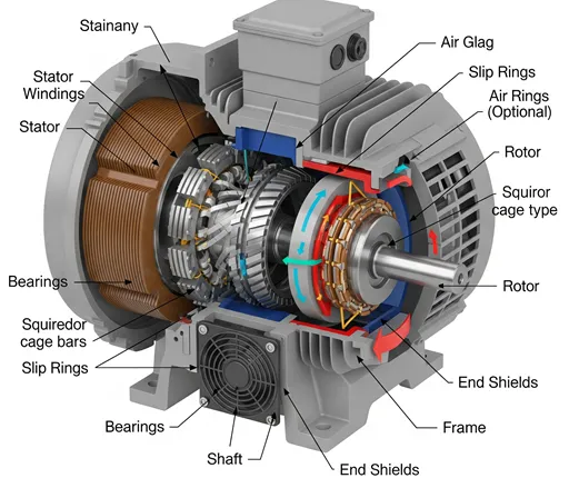
What is Stator?
The stator is the stationary part of an induction motor. It contains the stator windings, which are connected to the power supply. When AC voltage is applied, it creates a rotating magnetic field that induces current in the rotor.
What is Rotor?
The rotor is the rotating part of the motor. It is placed inside the stator and turns as a result of the electromagnetic induction from the stator's rotating field. There are two main types of rotors: squirrel cage and wound rotor.
What is Stator Winding?
Stator windings are copper wires wound in slots on the stator core. These windings form the magnetic field when energized by AC current. The type of winding and its arrangement affect the performance of the motor.
What is Speed in Induction Motor?
Speed in an induction motor refers to how fast the rotor rotates. There are two types of speed to understand:
- Synchronous Speed (Ns): The speed at which the magnetic field in the stator rotates.
- Rotor Speed (Nr): The actual speed at which the rotor rotates, which is always slightly less than Ns in an induction motor.
Synchronous Speed Formula
Ns = (120 × f) / P
Where:
Ns = Synchronous speed (in RPM)
f = Supply frequency (in Hz)
P = Number of poles of the motor
Rotor Speed Formula
Nr = Ns × (1 - S)
Where:
Nr = Rotor speed (in RPM)
Ns = Synchronous speed (in RPM)
S = Slip (in decimal)
Example:
If a 4-pole motor runs at 50 Hz supply:
Ns = (120 × 50) / 4 = 1500 RPM
If slip is 4% (i.e. S = 0.04), then:
Nr = 1500 × (1 - 0.04) = 1440 RPM
What is Slip Ring?
Slip rings are used in wound rotor induction motors. They provide external access to the rotor windings through brushes, allowing resistance to be added during startup for better torque control. Slip rings rotate with the rotor.
What is Bearing?
Bearings support the rotor and allow it to spin freely inside the stator. They reduce friction and wear between moving parts and are critical for smooth motor operation.
What is End Shield?
The end shield (or end cover) is a metal cover on both sides of the motor housing. It holds the bearings in place and protects the internal parts of the motor.
What is Shaft?
The shaft is a central rod connected to the rotor. It transfers mechanical power from the motor to the connected load, such as a fan or conveyor belt.
What is Fan?
A fan is mounted on the rotor shaft and helps in cooling the motor by blowing air over the outer frame. It prevents overheating during continuous operation.
What is Frame?
The frame is the outer shell of the motor. It provides mechanical strength, houses all components, and helps dissipate heat generated during operation.
What is Air Gap?
The air gap is the small space between the stator and rotor. It is crucial for efficient electromagnetic induction. A smaller air gap improves performance but must be carefully maintained to avoid contact between rotor and stator.
What is Slip in Induction Motor?
Slip is the difference between the synchronous speed (Ns) and the actual rotor speed (Nr) of the motor. It is usually expressed as a percentage.
Slip Formula:
Slip (S) =
(Ns - Nr) / Ns × 100%
Where:
Ns = Synchronous speed (in RPM)
Nr = Rotor speed (in RPM)
What is Rotor Current Frequency?
The frequency of the rotor current depends on the slip. It is zero when the rotor speed equals the synchronous speed (no relative motion).
Rotor Current Frequency Formula:
fr = S × f
Where:
fr = Frequency of rotor current (Hz)
S = Slip (in decimal)
f = Supply frequency (Hz)
What is Torque in Induction Motor?
Torque is the turning force generated by the motor to rotate the rotor and drive the mechanical load. It depends on rotor current and slip.
Torque Formula (Simplified):
T ∝ (s * E22) / (R22 + (sX2)2)
Where:
T = Torque
s = Slip
E2 = Rotor induced EMF
R2 = Rotor resistance
X2 = Rotor reactance
At low slip, torque is proportional to slip; at high slip (during starting), torque increases as slip increases.
What is a Carbon Brush?
A carbon brush is a small, block-like electrical conductor made of carbon or graphite. It is used in electric motors and generators to conduct current between the rotating part (rotor or commutator) and the stationary part (stator or external circuit).
Function of Carbon Brush
- Transfers current from the stationary wires to the rotating part.
- Maintains electrical contact with the rotating commutator or slip ring.
- Ensures smooth operation and reduces electrical arcing and wear.
Where is it used?
Carbon brushes are commonly used in:
- DC motors
- Slip ring induction motors
- Alternators and generators
- Power tools like drills and grinders
Why Carbon is Used?
- Carbon is a good conductor of electricity.
- It provides self-lubricating properties which reduce wear.
- It causes minimal damage to rotating parts during contact.