What Are the Main Components of a Motor Starter and Their Functions
Published on July 8, 2024 | Category: componentShare this Page:
A motor starter is a vital electrical device used to initiate, control, and protect an electric motor, especially in industrial environments where three-phase squirrel cage induction motors are commonly used. It ensures smooth motor operation by controlling inrush current, reducing mechanical stress during startup, and safeguarding against overload and short circuits.
Motor starters consist of multiple interconnected components, each with a specific role in the motor control system. The key elements typically include a magnetic contactor, thermal or electronic overload relay, and auxiliary contacts. Depending on the type of starter (e.g., DOL or Star-Delta), it may also include timers, control buttons, MCBs, fuses, and status indicators.
These components work together within a protective enclosure or panel, forming a coordinated system that automates motor control while maintaining operator and equipment safety. The selection and combination of components depend on motor rating, application type, and required protection level.
Note:
1. In a Direct-On-Line (DOL) starter, components are arranged for simple, full-voltage motor starting. It usually consists of an MCB/fuse, power contactor, overload relay, and auxiliary circuit.
2. In automatic Star-Delta starters, timers and additional contactors are added to manage the transition from star to delta during motor acceleration.
3. Accessories such as push buttons, selector switches, indication lamps, and wiring terminals help enhance user control and system diagnostics.
Below is a detailed explanation of each main component used in motor starters, along with its purpose and functionality:
What is Power Contactor
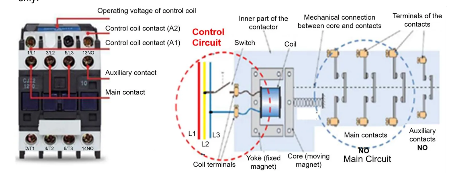
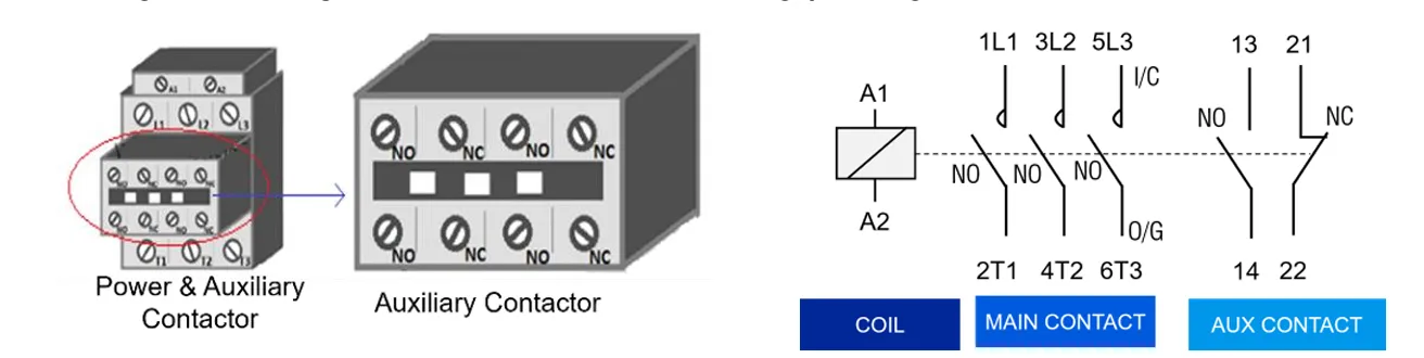
A power contactor is an electrically controlled switch used to control the flow of electrical power in motor starter circuits. It is designed to handle high current loads and acts like a relay but for power applications. The contacts inside a contactor are normally open (NO) and close when the electromagnetic coil is energized, allowing current to flow to the motor.
Power contactors may include both main power contacts and auxiliary contacts. While the power contacts manage the motor’s power connection, auxiliary contacts are used in the control circuit to signal or interlock functions.
Function
The primary function of a power contactor is to switch electrical power to motors and other heavy loads on and off. It enables remote control, automation, and safety isolation of the motor. Contactors are especially useful in repetitive operations and automatic motor starting systems.
Uses
- Starting and stopping 3-phase motors in industrial automation
- Remote switching of high-current loads
- Interlocking systems in motor control panels
- Used in HVAC systems, lighting control, and power distribution panels
- Works with timers and overload relays in DOL and Star-Delta starters
What is Thermal Overload Relay / Protection
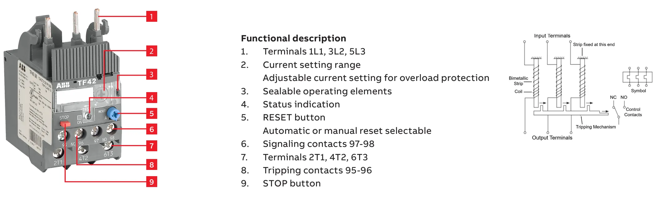
A Thermal Overload Relay is a critical protective component used in motor starters to safeguard electric motors from excessive current or overheating caused by prolonged overload conditions. It is designed to mimic the thermal behavior of a motor and trips the circuit when the motor operates beyond its safe temperature range.
This relay uses a bimetallic strip—two metals with different expansion rates bonded together. As current flows through the relay, the strip heats up. When the motor draws excessive current for an extended time, the strip bends and triggers a mechanism that opens the control circuit, thereby stopping the motor to prevent insulation failure or permanent damage.
Function
The function of a thermal overload relay is to continuously monitor the motor current and provide delayed tripping under overload conditions. It allows brief current surges during startup but disconnects the motor if high current persists beyond the safe threshold. It helps ensure long motor life by avoiding overheating and thermal stress.
Uses
- Protection against sustained motor overloads
- Automatically disconnects motors when overcurrent conditions occur
- Used in DOL, Star-Delta, and Soft Starters for thermal protection
- Ensures motor safety in pumps, compressors, conveyors, and fans
- Can be reset manually or automatically after tripping
What is Circuit Breaker / Fuse
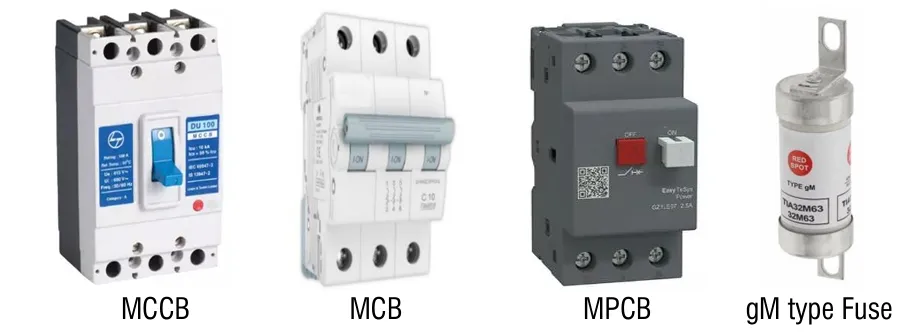
A Circuit Breaker or Fuse is a protective device used in motor starter panels to safeguard the motor and starter components from short-circuit conditions and high fault currents. These devices interrupt the power supply instantly when a fault, such as a phase-to-phase or phase-to-ground short circuit, occurs.
A fuse contains a thin metallic wire that melts when current exceeds a specific value, permanently breaking the circuit. On the other hand, a circuit breaker is an electromechanical device that automatically trips the circuit and can be reset after the fault is cleared. Both are essential for preventing fire hazards, equipment damage, and ensuring safe motor operation.
Function
The function of a circuit breaker or fuse is to detect and disconnect the power supply during short circuits or extreme overcurrent events. This prevents damage to the motor starter, power cables, and the connected equipment.
Uses
- Protection against short circuits and high fault currents
- Prevents electrical fires and equipment damage
- Installed at the input of the motor starter circuit
- Used in both low-voltage and industrial motor control systems
- MCBs allow reset after trip; fuses require replacement
What are Push Buttons
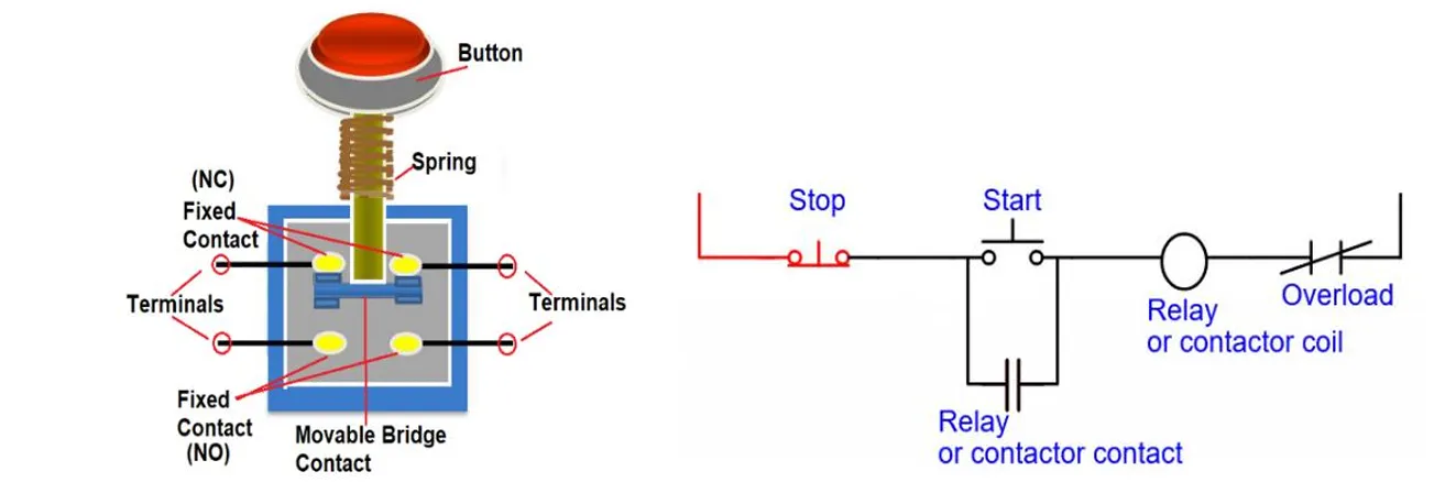
Push Buttons are manual control devices used to operate the motor starter. They provide a simple interface for the user to start or stop the motor. Typically, two push buttons are used: a Start button (normally open) and a Stop button (normally closed). When pressed, these buttons control the contactor coil, thereby managing the motor’s power flow.
The Start Button allows current to flow to the contactor coil, energizing it and starting the motor. The Stop Button breaks the control circuit, de-energizing the contactor and stopping the motor. These buttons are commonly mounted on the motor starter enclosure or control panel for easy access.
Function
Push buttons provide manual ON/OFF control of the motor. They serve as the operator’s interface with the motor control system, enabling safe and direct engagement or disengagement of motor operation.
Uses
- Manual control of motor starters in industrial and commercial panels
- Starting and stopping of motors in machines and conveyors
- Used in DOL, Star-Delta, and soft starter panels
- Acts as input in basic and advanced control circuits
- Can be color-coded and illuminated for status indication
What are Auxiliary / Feedback Contacts
Auxiliary Contacts, also known as Feedback Contacts, are secondary contacts used in motor starters for control and signaling purposes. They do not carry the main motor current but provide essential feedback and logic control for the starter system. These contacts change their state when the associated main contactor is energized or de-energized.
Generally, the auxiliary contacts used in motor starters are mechanically linked with the mechanism of the power contactor. This ensures that the auxiliary contacts accurately reflect the real-time state (ON/OFF) of the power circuit, enabling reliable operation of indicators, interlocks, and control circuits.
Auxiliary contacts are commonly used for interlocking, motor status indication, alarm triggering, and sequencing operations. They are available in Normally Open (NO) and Normally Closed (NC) types depending on the intended control logic.
Function
The function of auxiliary contacts is to enhance control logic by providing feedback or signal outputs based on the state of the motor contactor. They are widely used in automation systems for safety interlocks and coordinated operations of multiple devices.
Uses
- Indicating motor ON/OFF status with pilot lamps
- Creating interlocks in forward/reverse starter circuits
- Triggering alarms or safety shutdowns
- Providing status feedback to PLCs or control systems
- Used in SCADA/HMI systems for visual monitoring
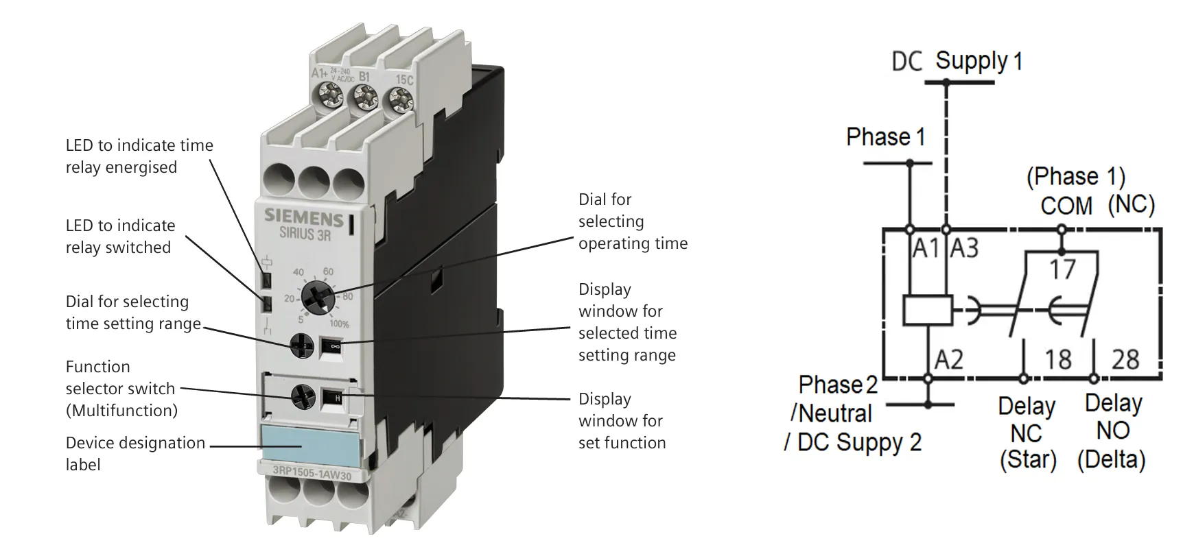
What is a Time Relay (Timer)
A Time Relay is a control device used to introduce a delay in electrical circuits, particularly in motor starter applications. It is most commonly found in Star-Delta starters, where it manages the time delay between the star connection (low voltage startup) and delta connection (full voltage running). This ensures a smooth transition, minimizing inrush current and mechanical stress on the motor.
Time relays are typically adjustable and can be set for specific time durations based on motor capacity and application needs. They operate by energizing or de-energizing contacts after a preset time delay, and may use analog dials or digital settings for time configuration.
In most cases, the timer is only included in starters that require a transition phase, such as Star-Delta starters. It is considered an optional component in basic starters like Direct-On-Line (DOL) starters where no timing function is needed.
Function
The primary function of a time relay is to control the switching time between different motor connection modes. In Star-Delta starters, it ensures the motor starts in star mode and then automatically switches to delta mode after a set time, preventing current surges and mechanical shocks.
Uses
- Used in Star-Delta starters for automatic transition control
- Introduces time delay in control logic circuits
- Prevents simultaneous energizing of both star and delta contactors
- Can be used in sequential motor start systems
- Ensures smoother motor acceleration and improved longevity
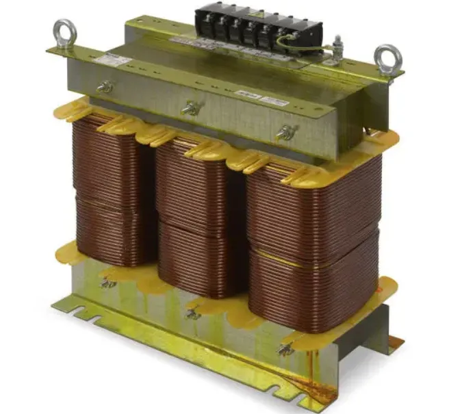
What is an Auto-Transformer
An Auto-Transformer is a special type of transformer used in Auto-Transformer Starters to reduce the initial voltage supplied to an induction motor during startup. By lowering the voltage, the motor draws less current and experiences reduced mechanical stress, making it ideal for high-power motors where direct starting is not suitable.
The auto-transformer has multiple tapping points on its winding, which provide different voltage levels (typically 50%, 65%, or 80% of full line voltage) depending on motor starting requirements. These voltage levels are selected by connecting the motor to different transformer terminals during the start cycle.
The main input terminals of the auto-transformer are connected to the incoming three-phase power supply through a Transformer Contactor. The reduced voltage output terminals are connected to the motor through a Shorting Contactor. Once the motor reaches a certain speed, the control circuit switches the motor to full-line voltage by bypassing the transformer.
Function
The function of an auto-transformer in a starter is to provide a stepped-down voltage during the motor's startup phase. This reduces inrush current and torque, ensuring smooth acceleration. After a preset time or speed is achieved, the motor is connected directly to the full voltage supply.
Uses
- Used in auto-transformer starters for large motors
- Reduces voltage and current during startup to limit mechanical and electrical stress
- Ideal for motors with high starting torque requirements
- Commonly used in pumps, compressors, and heavy-duty conveyors
- Improves motor life and reduces power system disturbances
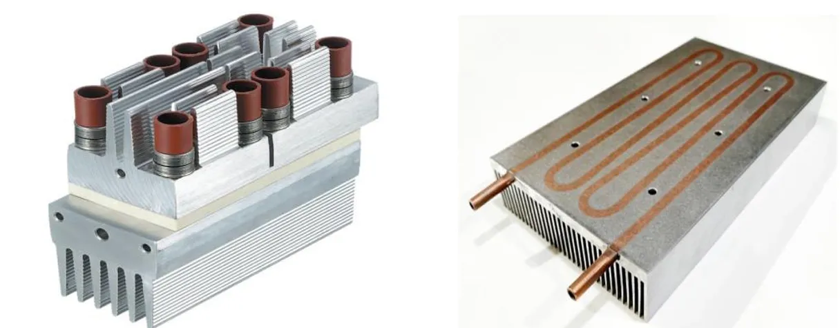
What is a Heat Sink
A Heat Sink is a passive thermal management component used to dissipate heat generated by power electronic devices such as SCRs (Silicon Controlled Rectifiers) or TRIACs in soft starters and motor control circuits. Excess heat must be managed to prevent damage or performance degradation in sensitive semiconductor components.
Heat sinks are typically made of aluminum or copper and feature a series of metal fins that increase the surface area for efficient heat dissipation through conduction and convection. They are often mounted directly on the semiconductor devices using thermal paste or insulating pads to maximize heat transfer.
Function
To absorb and transfer heat away from high-temperature components, preventing overheating and ensuring safe, efficient operation of motor starter electronics.
Uses
- Attached to SCRs or TRIACs in soft starters
- Used in power modules and solid-state relays
- Improves longevity and thermal performance of control devices
- Protects devices from thermal shutdown or failure
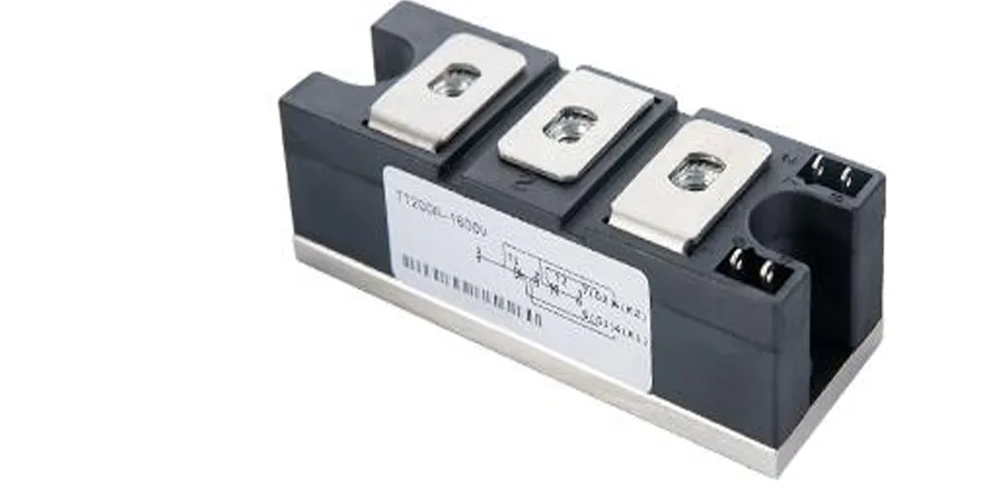
What is a Rectifier in Soft Starter / VFD
A Rectifier is a semiconductor-based circuit that converts AC (alternating current) input to DC (direct current). In motor control systems like Soft Starters and Variable Frequency Drives (VFDs), rectifiers play a critical role in conditioning the incoming power supply for controlled motor acceleration and speed regulation.
There are various types of rectifiers used depending on the configuration and power rating. These include half-wave, full-wave, bridge, and anti-parallel designs. The choice of rectifier depends on the type of motor starter and the level of control required.
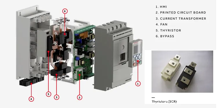
In Soft Starters, rectification is typically done using TRIACs for small motors and SCRs (Silicon Controlled Rectifiers) in anti-parallel configuration for larger motors. These semiconductors allow gradual application of voltage during startup, reducing mechanical and electrical stress on the motor.
In VFDs, rectifiers are more advanced. A common design is the 6-pulse rectifier, which uses diodes and thyristors to convert the incoming AC into DC. This DC is then fed to an inverter circuit to create a variable-frequency AC output, allowing precise control over motor speed and torque.
Function
The rectifier converts AC to DC in the first stage of power processing. In soft starters, it enables gradual motor voltage ramp-up. In VFDs, it supplies the DC link for the inverter stage. The rectifier directly impacts the quality, efficiency, and control smoothness of the motor startup or speed regulation process.
Uses
- Used in Soft Starters to control motor voltage during startup
- Used in VFDs to convert AC to DC before inverter stage
- Allows smooth, jerk-free motor startup and speed control
- Protects motors from inrush current and electrical shock loads
- TRIACs used in low-rating motors; SCRs in large-rating applications
- VFDs typically use 6-pulse diode/thyristor-based bridge rectifiers
What are Power Switches (IGBTs / MOSFETs)
Power Switching Devices such as IGBTs (Insulated Gate Bipolar Transistors) and MOSFETs (Metal-Oxide-Semiconductor Field-Effect Transistors) are essential components in inverter-based motor control systems. These switches are responsible for converting the filtered DC voltage into a variable AC output by turning ON and OFF rapidly in a controlled sequence.
By adjusting the timing and duration of these switching events — a method known as PWM (Pulse Width Modulation) — the inverter can precisely control both the frequency and the amplitude of the AC signal delivered to the motor. This results in smooth motor speed control and high efficiency.
MOSFETs are generally used for low-voltage, high-speed switching applications, while IGBTs are preferred for higher voltage and power levels typical in industrial motor starters or soft starter-inverter hybrids.
Function
To switch DC current in a timed manner to produce a variable-frequency, variable-voltage AC output for controlling motor speed and torque.
Uses
- Used in inverter circuits of advanced soft starters and hybrid starters
- Control output frequency and voltage to drive the motor
- Enable efficient motor speed regulation with reduced harmonic distortion
- Widely used in industrial automation and HVAC motor control
What is a Microcontroller or Control Circuit in a Soft Starter
The Microcontroller or control circuit in a Soft Starter acts as the brain of the system. It continuously monitors inputs, processes control algorithms, and coordinates the operation of power electronics to ensure smooth and safe motor startup. The microcontroller evaluates parameters such as motor voltage, current, and thermal condition to execute soft-start logic precisely.
One of its primary tasks is to regulate the firing angles of the thyristors (SCRs) used in the power circuit. By controlling when these SCRs turn on within each AC cycle, the microcontroller can gradually increase the voltage applied to the motor, reducing inrush current and mechanical shock.
Gate Firing Circuit in Soft Starter
The Gate Firing Circuit is a critical part of the control system that delivers precisely timed signals to the gates of the SCRs. These firing pulses determine the exact point in the AC waveform when the SCRs should conduct, effectively controlling the RMS voltage supplied to the motor.
The microcontroller dynamically adjusts the firing angles based on programmed ramp-up profiles and real-time motor feedback. This controlled voltage ramp allows for a smooth increase in motor torque and speed during startup, avoiding sudden mechanical stress and electrical disturbances.
Function
The function of the microcontroller and gate firing circuit is to execute soft start and soft stop operations through phase angle control. It ensures that voltage is applied in a controlled and progressive manner, maintaining motor health and system efficiency.
Uses
- Used in soft starters to manage SCR triggering for smooth startup
- Controls voltage ramp-up and ramp-down profiles
- Reduces motor wear, mechanical impact, and power surges
- Receives inputs like start command, motor load, or fault feedback
- Ensures precise and programmable motor startup sequences
What is a DC Bus or Filter in VFD
The DC Bus or DC Link in a VFD (Variable Frequency Drive) is an intermediate power stage that stores and stabilizes the DC voltage after rectification and before inversion. Once the AC supply is converted into DC by the rectifier, this DC voltage passes through the DC link where it is filtered and stored.
The DC bus typically includes a combination of capacitors and inductors, forming an LC filter. This configuration smooths out voltage fluctuations, eliminates high-frequency ripple, and reduces harmonic distortion, ensuring a stable DC supply to the inverter stage.
What is an Inverter in VFD
The Inverter is the final stage of a VFD that converts filtered DC voltage from the DC bus into a variable-frequency and variable-voltage AC output. This allows the motor to run at controlled speed and torque by adjusting the AC frequency and amplitude.
Power Switches (IGBTs / MOSFETs)
The inverter uses Power Switching Devices such as IGBTs (Insulated Gate Bipolar Transistors) or MOSFETs (Metal-Oxide-Semiconductor Field-Effect Transistors) to convert DC to AC. These switches rapidly turn ON and OFF to produce pulse-width modulated (PWM) AC signals.
What is a Bypass Contactor
A Bypass Contactor is used in soft starters to improve efficiency once the motor reaches its full speed. After the soft start phase is completed, the bypass contactor connects the motor directly to the power supply, allowing the SCRs to be bypassed and reducing heat generation and power loss.
This improves energy efficiency, extends the life of the soft starter components, and is standard in most modern soft starters.
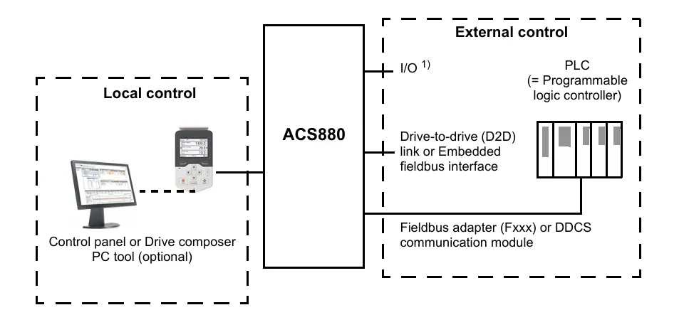
What is a Communication Module
Modern VFDs and soft starters often include or support optional communication modules like Modbus RTU, Profibus, EtherNet/IP, or Profinet. These modules enable remote monitoring, control, and data logging via PLCs, SCADA, or cloud systems.
They play a key role in industrial automation and IIoT (Industrial Internet of Things).
What is a Brake Chopper or Dynamic Braking Resistor
In applications where the motor decelerates quickly (e.g., elevators, cranes), a Brake Chopper circuit is used to dissipate excess regenerative energy. It prevents overvoltage on the DC bus by diverting excess current to an external braking resistor.
This ensures smooth deceleration and prevents damage to the VFD during dynamic braking conditions.