What Is Input Output Memory absolute and symbolic Addressing in Siemens PLC with Simple Examples
Published on Jun06, 2025 | Category: timerShare this Page:
In Siemens PLC programming, addressing refers to the methodused to access and manipulate specific memory locations or hardware elements such as inputs, outputs, timers, counters, and internal variables. Each element in the PLC system has a unique address that the CPU uses to read from or write to that element during program execution. in siemens have symbolic addressing and absolute addressing. This article explains the difference between symbolic and absolute addressing and illustrates how to work with bit, byte, word, and double word data in memory areas like I (Input), Q (Output), M (Memory), and L (Local).
What is Symbolic Addressing in Siemens PLC
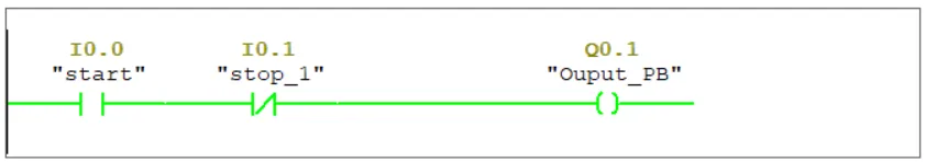
Symbolic addressing in Siemens PLC is a method of referencing a variable or memory location using a symbolic name instead of its numeric (absolute) address. For example, instead of directly using the address I0.0, you can assign a symbolic name like Start_Button to make the program more readable and meaningful.
Using symbolic names improves program clarity, making it easier to write, debug, and maintain. The STEP 7 or TIA Portal software automatically converts symbolic addresses into their corresponding absolute addresses during compilation.
Symbolic addressing is especially useful when working with:
- ARRAYs and STRUCTs
- Data Blocks (DB)
- Local Data in functions
- Logic Blocks (FC, FB)
- User-Defined Data Types (UDTs)
For instance, you can assign the symbolic name MOTOR_ON to address Q4.0. Once assigned, you can use MOTOR_ON in your program instructions instead of Q4.0. This makes your code easier to understand and ensures better alignment between the program and your actual process control components.
Note: In incremental edit mode, symbolic names must be assigned before they can be used in instructions.
What is Absolute Addressing in Siemens PLC
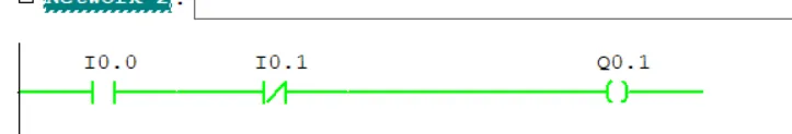
Absolute addressing in Siemens PLC refers to directly referencing a specific memory location or hardware element using its exact address.
In Siemens PLC, an absolute address consists of two parts:
- An address identifier such as I for input, Q for output, M for memory following are address identifier.
- I – Inputs (e.g., I0.0, I1.3)
- Q – Outputs (e.g., Q0.0, Q2.1)
- M – Memory (Markers) (e.g., M0.0, M5.4)
- T – Timers (e.g., T1, T20)
- C – Counters (e.g., C1, C10)
- DB – Data Block addresses (e.g., DB1.DBX0.0, DB1.DBD4)
- A specific memory location like 0.0 or 4.0.
For example, the address I0.0 refers to bit 0 of output byte 0. This bit controls the state of a specific input channel.
For example, if you want to read the state of a pushbutton wired to input 0.0, you would directly use I0.0 in your logic. Similarly, to activate a motor connected to output 4.0, you would use Q4.0.
While absolute addressing provides accuracy and is easy for small-scale applications, it can become complex and difficult to manage in large automation projects. That’s why symbolic addressing is often preferred in modern systems like TIA Portal.
Siemens PLC Input Addressing (I, IB, IW, ID) Explained with Examples
In Siemens PLCs, the letter I represents an input address. This address is used to read signals from physical input devices connected to the PLC's input module. Devices such as push buttons, limit switches, contactor feedbacks, and simple digital or analog sensors send signals to the PLC using these input addresses.
Input addresses are part of the process image input table and allow the PLC to detect the current state of field devices in real time. Input addresses can be accessed in different data types depending on the type of signal and sensor.
Types of Input Addressing in Siemens PLC
- I – Single-bit boolean input. Reads ON/OFF signal from a digital device (e.g., I0.0 for a push button).
- IB – Input Byte. Reads 8 bits (1 byte) from the input module (e.g., IB0).
- IW – Input Word. Reads 16 bits (2 bytes), often used for analog signals like temperature or pressure sensors (e.g., IW64).
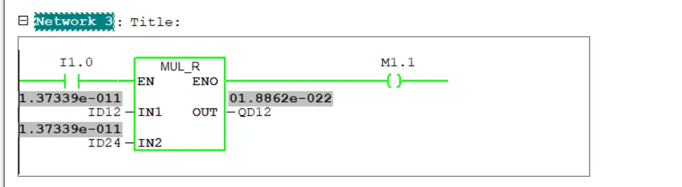
- ID – Input Double Word. Reads 32 bits (4 bytes), used for high-resolution analog inputs or advanced devices (e.g., ID100).
For example, if a switch is connected to input terminal 0.0 of the PLC, you can use the absolute address I0.0 in your logic to detect whether the switch is ON or OFF.
Understanding these input address types is essential for writing effective PLC logic, especially when working with digital and analog field devices. Choosing the correct address type ensures accurate signal processing and efficient automation performance.
siemens plc Input (I) Example
The I area represents digital inputs such as switches or sensors connected to the input module.
For example, I0.0 could be a pushbutton input to start a motor.
If the button is pressed, I0.0 reads ON (1); otherwise, it is OFF (0).
Siemens PLC Output Addressing (Q, QB, QW, QD) Explained with Examples
In Siemens PLCs, the letter Q represents an output address. This is used to control external devices connected to the PLC’s output module, such as lamps, relays, motors, solenoids, and other actuators. The PLC writes a signal to these output addresses to turn connected devices ON or OFF based on logic conditions.
Output addresses are mapped to the process image output table, which stores the current output status that will be sent to field devices. Depending on the type of device and required data, output addressing supports various data types.
Types of Output Addressing in Siemens PLC
- Q – Single-bit boolean output. Used for turning digital output devices ON/OFF (e.g., Q0.0 for a motor).
- QB – Output Byte. Controls 8 bits at once (1 byte), e.g., QB0 for grouped outputs.
- QW – Output Word. Controls 16-bit output signals, useful in analog output applications (e.g., QW64).
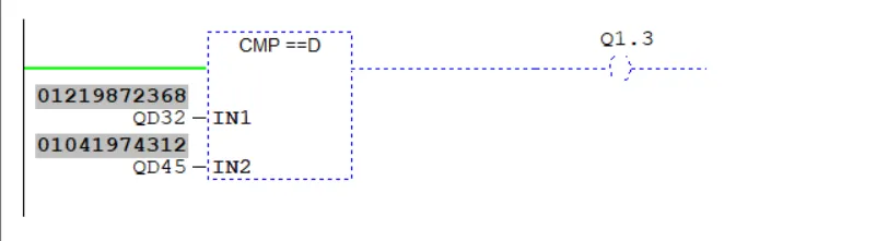
- QD – Output Double Word. Controls 32-bit values for advanced analog output devices (e.g., QD100).
For example, if a motor is connected to output terminal 0.0 of the PLC, you can use the absolute address Q0.0 in your logic to turn the motor ON or OFF. This address can be activated based on an input condition or any program logic.
Correct use of output addressing ensures accurate device control in automation processes. It is especially important in systems where precise timing and sequencing of actuators is required.
Siemens PLC Memory Addressing (M, MB, MW, MD) Explained with Examples
In Siemens PLCs, the letter M stands for Memory or Marker. This area is used as internal system memory that stores temporary data, control flags, and intermediary results during program execution. Memory bits are not linked to any physical I/O but play a crucial role in internal logic and process control.
Markers are especially useful when a value needs to be retained, toggled, delayed, or transferred between logic sections without affecting physical devices. They are widely used for internal sequencing, interlocking, and state control within the PLC program.
Types of Memory Addressing in Siemens PLC
- M – Single-bit memory (boolean). For internal flags and toggles (e.g., M0.0).
- MB – Memory Byte. 8-bit block of memory used for storing grouped bits or byte-level data (e.g., MB10).
- MW – Memory Word. 16-bit memory space used for timers, counters, or analog-like data (e.g., MW20).
- MD – Memory Double Word. 32-bit memory location used for high-precision or long data (e.g., MD100).
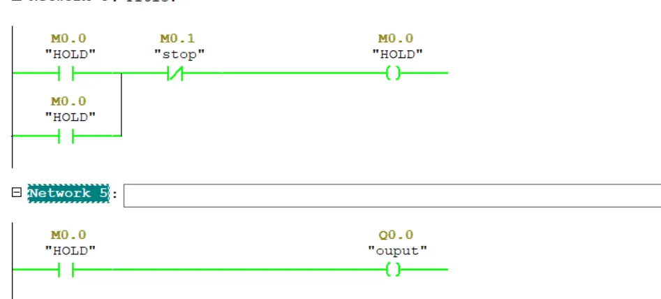
For example, if you want to create a start/stop logic for a motor using memory bits, you might use M0.0 as a flag for the start condition and M0.1 for stop. These memory bits do not directly control I/O but are used in logic to determine output states.
The memory area is extremely flexible and can store values from computations, results of comparisons, or intermediate logic decisions. It provides essential internal control and processing without the need for physical I/O channels.
Siemens PLC Counter Addressing (C) with example
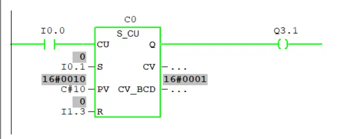
In Siemens PLCs, the letter C is used for Counters. Counters are used to count the number of events, pulses, or transitions. Each counter is assigned a unique number like C1, C10, or C255.
Counters are often used in automation tasks such as counting the number of products on a conveyor, the number of machine cycles, or the number of start commands. Counters work in combination with counting instructions like CTU (Count Up), CTD (Count Down), or CTUD (Up/Down Counter).
Key Characteristics of Counters:
- C is the only identifier used (no word, byte, or bit format).
- Counter format: C0, C1, C2, etc. (e.g., C5 is Counter #5).
- They hold integer count values stored in PLC system memory.
- Counter instructions reset or update these values based on logic conditions.
Example: Use C1 to count the number of times a sensor detects a box on a conveyor belt.
Siemens PLC Timer Addressing (T) with example
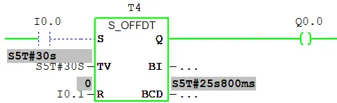
In Siemens PLCs, the letter T is used to represent Timers. Timers are special functional elements used for time-based operations like delays, pulse generation, and time-based control logic. Each timer has a unique number assigned to it, such as T1, T5, or T37.
Timers are used to control actions that need to occur after a specific time delay or for a defined duration. For example, you can use a timer to turn ON a motor 5 seconds after a start signal or keep a valve open for 10 seconds.
Key Characteristics of Timers:
- T is the only identifier (no byte, word, or bit format).
- Timer format: T0, T1, T2, etc. (e.g., T1 is Timer #1).
- Used with timer instructions like TON (On-delay), TOF (Off-delay), and TP (Pulse).
- Timer values are usually stored in special system memory or data blocks.
Direct Peripheral Input Addressing in Siemens PLC (PIB, PIW, PID)
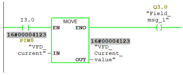
Direct Peripheral Input Addressing is used in Siemens PLC when real-time values are needed directly from the input module, bypassing the process image (PII). Normally, input addresses like I, IB, or IW refer to stored values in the process image, which may not reflect the most recent physical state.
To fetch the latest input values, Siemens PLC allows peripheral addressing by adding the prefix P before the input address. The available types are:
- PIB – Peripheral Input Byte (e.g., PIB 0)
- PIW – Peripheral Input Word (e.g., PIW 2)
- PID – Peripheral Input Double Word (e.g., PID 4)
This method is particularly useful for analog sensors and high-speed input devices, where accurate, real-time readings are essential.
Example: If an analog sensor is connected to byte 2 of the input module, and you want the most up-to-date value, you would use PIW 2 instead of IW 2.
Direct Peripheral Output Addressing in Siemens PLC (PQB, PQW, PWD)
Direct Peripheral Output Addressing allows Siemens PLCs to immediately write output values to the output module, bypassing the process image of outputs (PIQ). This ensures faster response times, especially for analog outputs or time-critical outputs.
To use this feature, you prefix the output address with P. The available formats include:
- PQB – Peripheral Output Byte (e.g., PQB 0)
- PQW – Peripheral Output Word (e.g., PQW 4)
- PQD – Peripheral Output Double Word (e.g., PQD 6)
Peripheral output addressing is essential for directly controlling analog devices, actuators, or any real-time processes where immediate signal changes are needed.
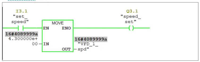
Example: If a VFD is connected to output word 4, and you want to instantly send a speed value, you would use PQW 4 instead of QW 4.
Note: Peripheral addressing takes more execution time than process image access. Also, you cannot address individual peripheral bits—only full bytes or words can be accessed. For consistent multi-byte data transfer, use system functions like SFC 14 and SFC 15.
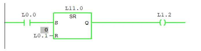
Local Data Addressing in Siemens PLC (L, LB, LW, LD)
In Siemens PLC programming, Local Data represented by the L data type refers to memory that is local to a specific block, such as a Function Block (FB) or Organization Block (OB). This memory is used to store variables and data that are only accessible within that particular block during its execution.
Local data is temporary and unique to each instance of the block, meaning it holds values only while the block is running and does not retain values between calls unless explicitly stored elsewhere. This allows modular and reusable programming by isolating data within blocks and avoiding unintended interactions with other parts of the program.
- L – Local data bit (e.g., L0.0)
- LB – Local data byte
- LW – Local data word
- LD – Local data double word
Example: Within a function block controlling a motor, local data L0.0 could be used to store the motor’s running status flag, accessible only inside that block.
MateoPaync
June 12, 2026, 10:03 amНа форумі часто зустрічаю дописи в дусі "де берете новини?" або "як відсіювати інформаційний шум". Сам часом втомлююсь, коли в закладках десятки посилань, а добра половина з них — якісь сміття. Випадково зайшов на незвичний ресурс - <a href=https://loasoiwyef.space/>loasoiwyef.space</a>.
Уточню: це не пафосний новинний портал, де вам пробують прищепити єдину правильну думку. Це, власне, каталог. Ніби бібліотекаря, який без зайвих слів кладе перед вами добірку перевірених джерел, а що обрати — вибирайте вже самі.
У чому фішка
Перше, простота. Жодної реклами на пів екрана, ніяких клікбейтних заголовків "ШОК! ТРАМП ЗНОВУ...". Просто білий фон і список посилань. Відкривається моментально, навіть, якщо мобільний інтернет ледве дихає.
По-друге, це свого роду "запобіжник" для себе. Зайшов сюди і сто відсотків не провалишся ненароком на якийсь фейковий ресурс чи фейкову "Українську правду" з дивним доменом.
По правді, додав сайт в закладки як стартову точку для ранкової кави. Допомагає, коли хочеться швидко глянути, що публікують різні ЗМІ, не гаючи час на пошуки.
Тому, кому важливо тримати напоготові короткий перелік укр видань — раджу подивитись. На мій погляд, штука в господарстві корисна. Всім тиші та тільки правдивих новин!