Your First SCADA Project in Siemens WinCC SCADA : Create Your First Project
Share this Page:
wincc scada is software used to design graphical user interface for industrial control system. in this software design screen(picture) and assign component like button, lamp, alarm system. wincc scada is widely used in large industrial process control. wincc connect almost all plc like AB, Siemens, ABB. you can also connect OPC server and sql server. in this article we create a simple SCADA project using WinCC in TIA Portal. This beginner-friendly guide covers basic SCADA screen(picture) design, PLC tag configuration, and real-time control setup for industrial automation. A simple project, in graphics designer design simple on off push button. assign tag and configure driver of plc and plc simulator.
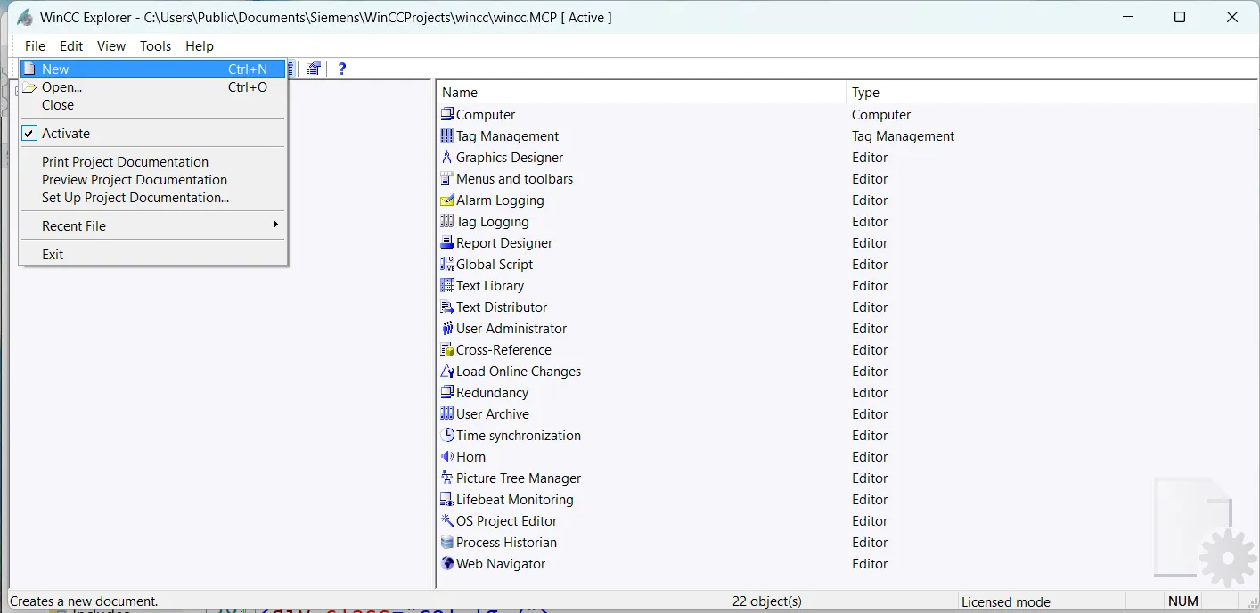
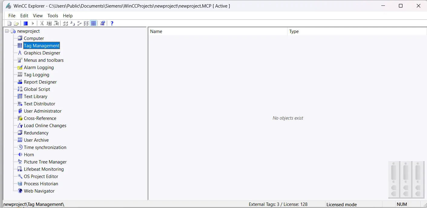
open wincc explorer and create a new project
open wincc explorer(Wincc control center) and create a new project. goto file new and then select single user project from pop windows
enter project name and select project path of your project and press create.
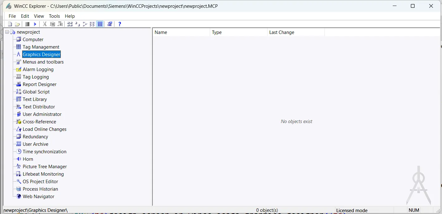
design screen in wincc scada graphics designer
after creating project open graphics designer from wincc explorer. and design picture for your industrial control system. here we simply add a button and a circle for learning purpose. and assign a tag in both component.
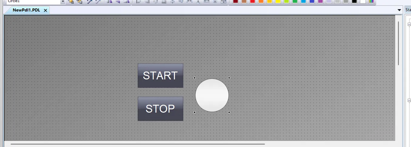
add picture component in wincc scada graphics designer
in this example project simply insert two button and circle. first button are used to start motor and second button are used to stop motor. a circle background color change red to green if motor start.
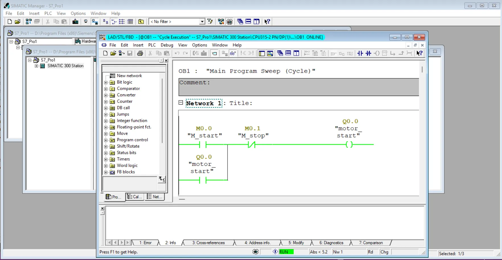
create a motor start and stop project in step 7
open Siemens step7 and configure plc and create a simple motor on and off project assign symbol for all address like M0.0 start and M0.1 stop motor and output Q0.0 is output of motor.after creating ladder logic test your project and download this project to your controller or simulator after successfully testing move to next step.
wincc tag management and driver configuration
after testing next step to connect plc or simulator to wincc control center. so open tag management than configure driver and insert tag and same address as your ladder logic or program for example our motor start address is M0.0 than we give same address in tag.
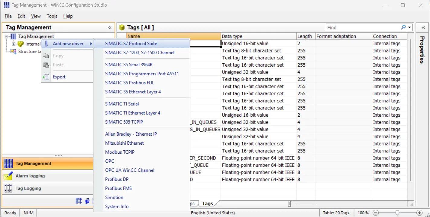
configure driver in wincc scada for plc simulator or controller
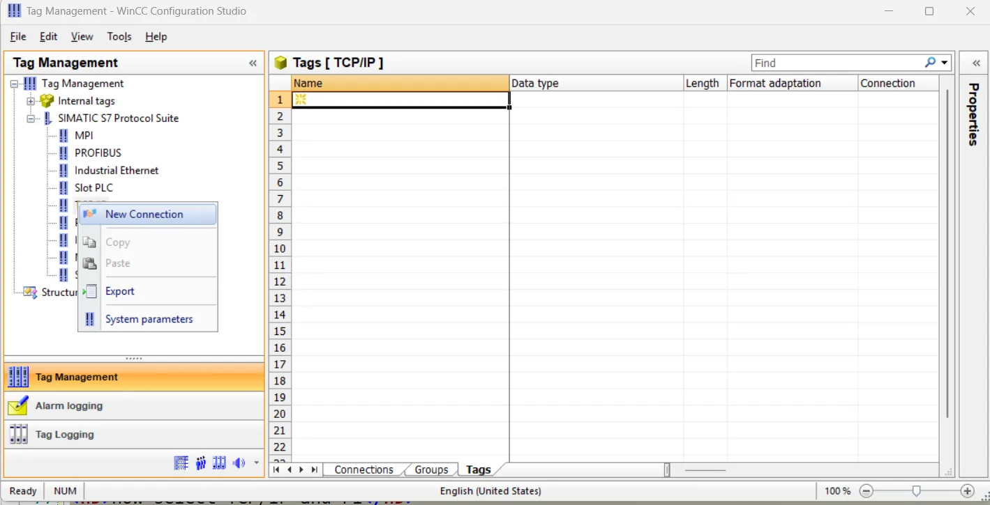
in tag management right click and select add new driver and select simatic s7 protocol suite.
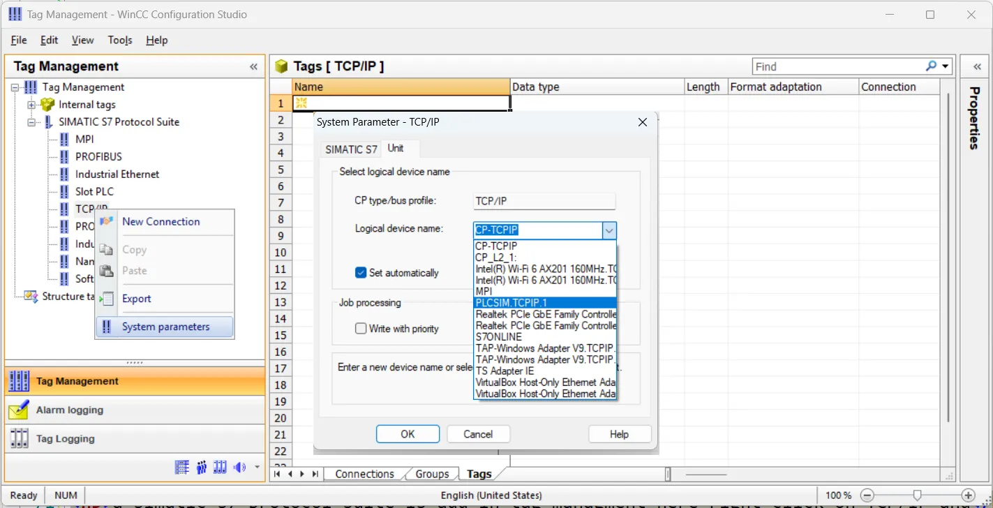
add system parameter for driver in wincc scada
a simatic s7 protocol suite is add in tag management here right click on TCP/IP and select system parameters. a system parameter dialog open here select unit tag and in logical device name select plcsim. tcpip and press ok
add a plc simulator connection in wincc scada
now select TCP/IP and right click and select new connection enter name or leave it default.
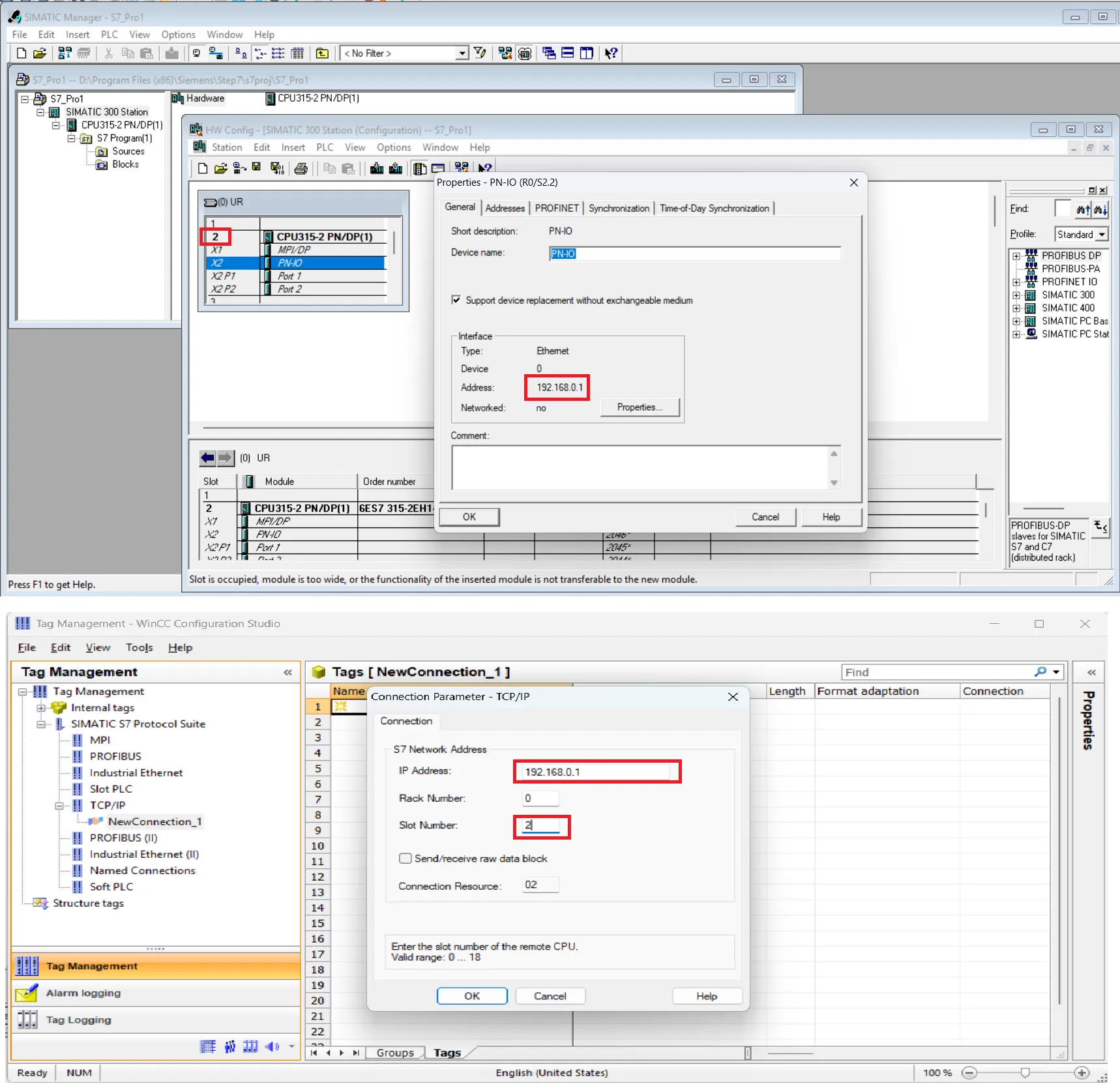
assign connection parameter for plc simulator in wincc scada
now right click on new connection and select connection parameters a connection parameter dialogue open here enter same ip address and slot number. for ip address and slot open step 7 and got to hardware configuration select pn-io and right down ip address as shown same ip address assign in network connection parameters. for slot address note down slot of plc. same step also required for plc. add slot and ip address press ok.
make online of step7 after all configuration and setting, and change plc simulator to run mode.
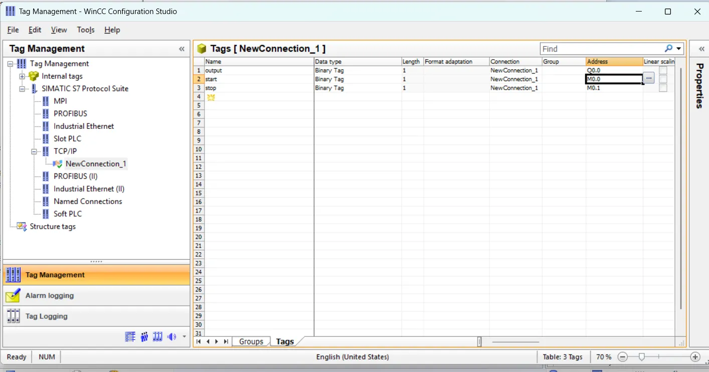
add tag in tag management wincc scada
now assign same address of tag in tag management as you assign in step 7 project.
assign tags in screen component in wincc graphics designer
now back to graphics designer and select component and assign tag. select button and got event tag select mouse click event and double click a direct dialog open here select constant and enter 1 in target select tag and open tag browser select start tag and then select direct and press ok. Repeat same for stop button.
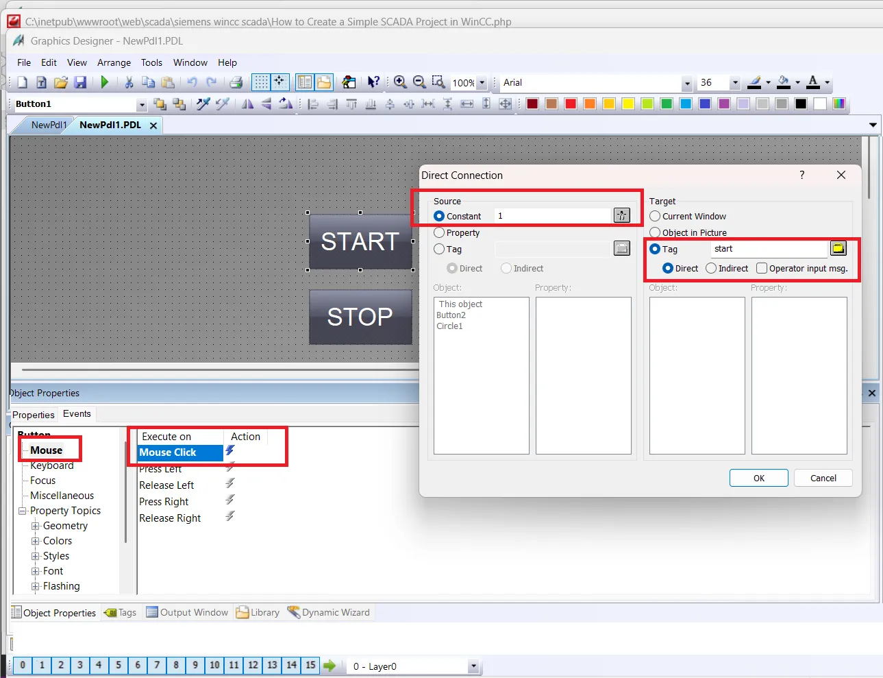
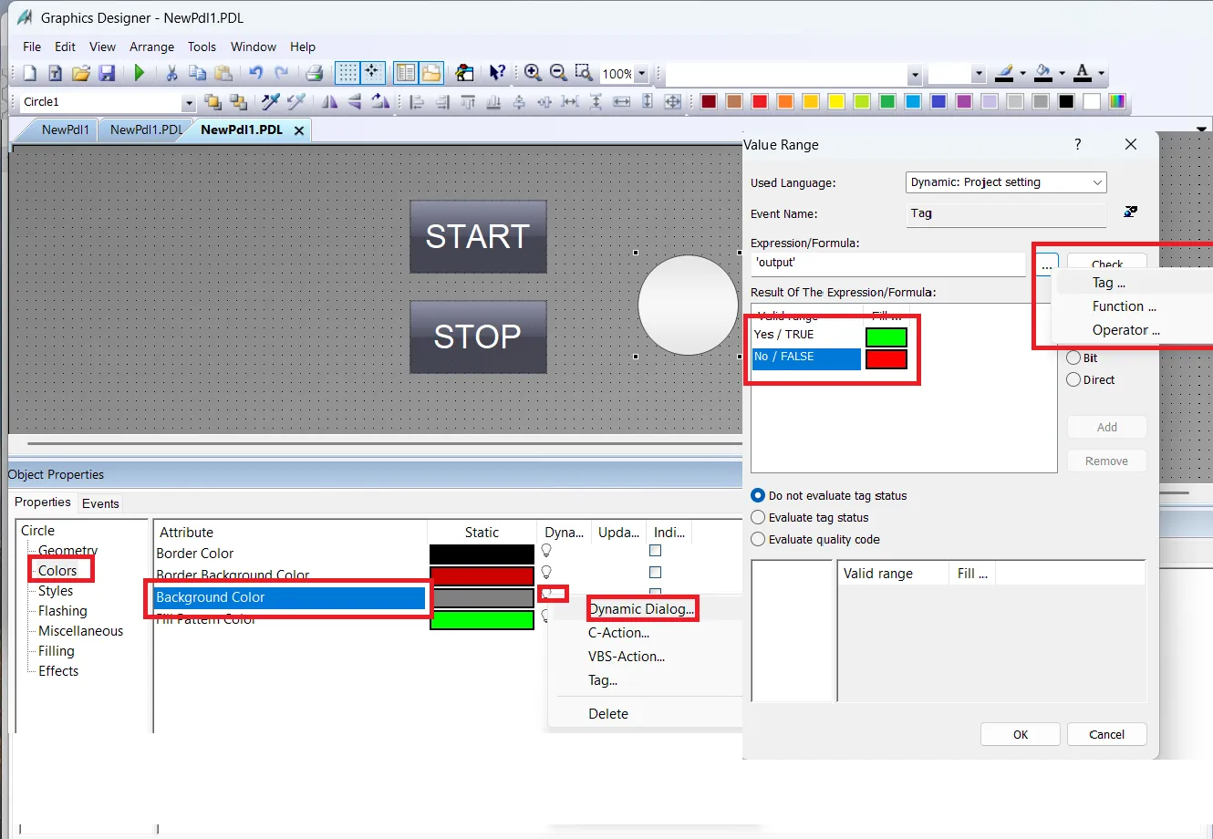
after assigning tag for both button select circle color property and than open background color dynamic property here select Boolean change color for true and false and then select tag from browser. In this article we select output. next select effects and set no in global color scheme. Save your project.
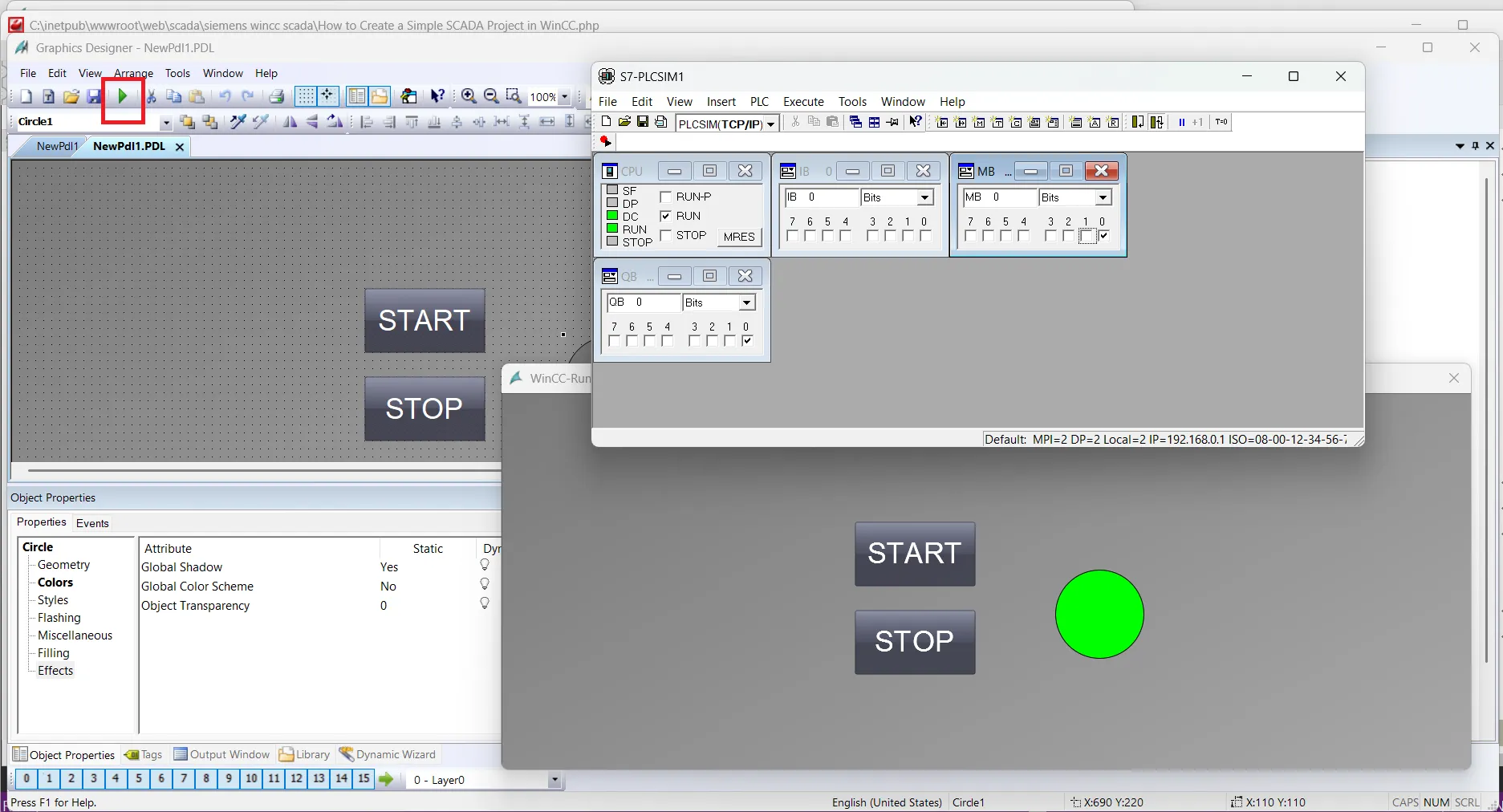
simulate wincc scada screen with plc simulator
now click to runtime to open wincc runtime. in your screen wincc runtime window open. check your program. if everything is right button start and stop change color of circle. in this program when start press color is changed to green and when stop button is pressed color changed to red.