Siemens WinCC SCADA Alarm Setup: Analog and Digital Alarm Configuration
Published on Jun18, 2025 | Category: alarmShare this Page:
The alarm system is one of the most essential features in modern industrial control systems. It is designed to alert users or plant operators about abnormal or critical conditions occurring during process automation. Alarms play a vital role in maintaining safety, reliability, and smooth operation of machinery by providing timely information about system behavior. When a specific predefined condition is met—such as a temperature exceeding its limit or a device failing to respond—the alarm system automatically triggers and displays a message to inform the operator. This message can indicate a warning, error, or normal status, depending on the severity of the situation. The operator is required to acknowledge the alarm, ensuring human intervention or corrective action is taken when needed. Alarm systems help troubleshoot faults, prevent equipment damage, and reduce downtime. In SCADA and HMI environments, alarms are usually shown using visual indicators like colored lights, text messages, and pop-up windows. Alarm messages can also be logged for future analysis and reporting. Whether it's a simple high-temperature warning or a critical system failure notification, a well-implemented alarm system is essential for efficient and safe process control.
Types of Alarms in Siemens WinCC SCADA: Normal, Warning, and Error
In Siemens WinCC SCADA, alarms are categorized based on the severity and urgency of the condition they represent. The three common types of alarms used in process automation are Normal, Warning, and Error. A Normal alarm indicates that the process is operating within acceptable parameters. A Warning alarm signals a potential issue or deviation that requires attention but does not immediately stop the process. An Error alarm indicates a critical condition or fault that must be addressed immediately to avoid equipment damage, safety risks, or system shutdown. Each type of alarm can be represented visually using color codes such as green for normal, yellow for warning, and red for error. Configuring these alarm types properly helps operators quickly identify and respond to abnormal conditions during runtime.
Siemens WinCC SCADA Tag for Alarm
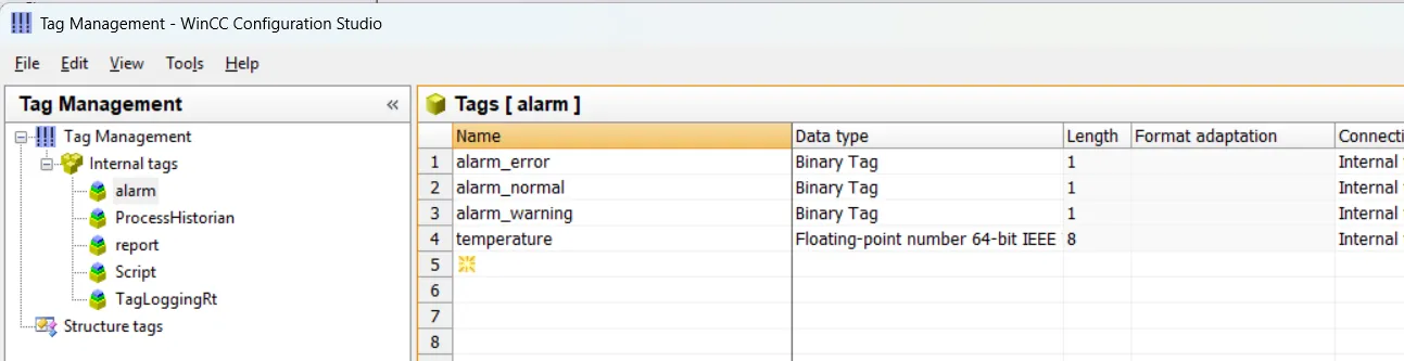
An alarm is triggered when a selected tag reaches a specific value, so it is important to configure the required tags properly. In this example, we will use a temperature tag to control the alarm logic. To begin, open Tag Management in WinCC and create the following tags:
- temperature – Data type: Float
- alarm_error – Data type: Boolean (BOOL)
- alarm_warning – Data type: Boolean (BOOL)
- alarm_normal – Data type: Boolean (BOOL)
These binary tags are used to indicate different alarm states, while the temperature tag serves as the condition input. When the temperature value crosses certain thresholds, the appropriate alarm bit will be activated and shown to the operator on the SCADA screen.
Siemens WinCC SCADA Graphics Components for Alarm
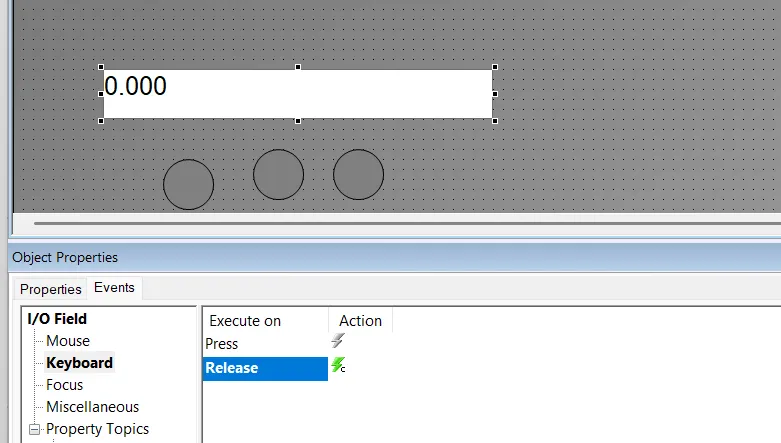
In Siemens WinCC SCADA, you can design a simple and effective alarm monitoring screen using graphical components. To visualize alarm status clearly for the operator, you can add three circular shapes representing different alarm levels—Error, Warning, and Normal. Alongside these, place an Input/Output Field to display or simulate the temperature value.
Each circle should be linked to a corresponding Boolean tag, such as alarm_error, alarm_warning, and alarm_normal. Based on the value of these tags, the background color of the circles will change dynamically:
- Error: Circle turns Red when the temperature exceeds the critical limit.
- Warning: Circle turns Yellow when the temperature is in the warning range.
- Normal: Circle turns Green when the temperature is within the safe range.
This visual indication allows the operator to quickly identify the current condition of the process. You can also enhance the screen by adding labels to each circle and using animations or color blink effects to grab attention in case of critical errors. The Input/Output field can be used to manually test the alarm ranges during runtime or connect to a PLC tag in real deployment.
C Action Script for Alarm Control in Screen Component
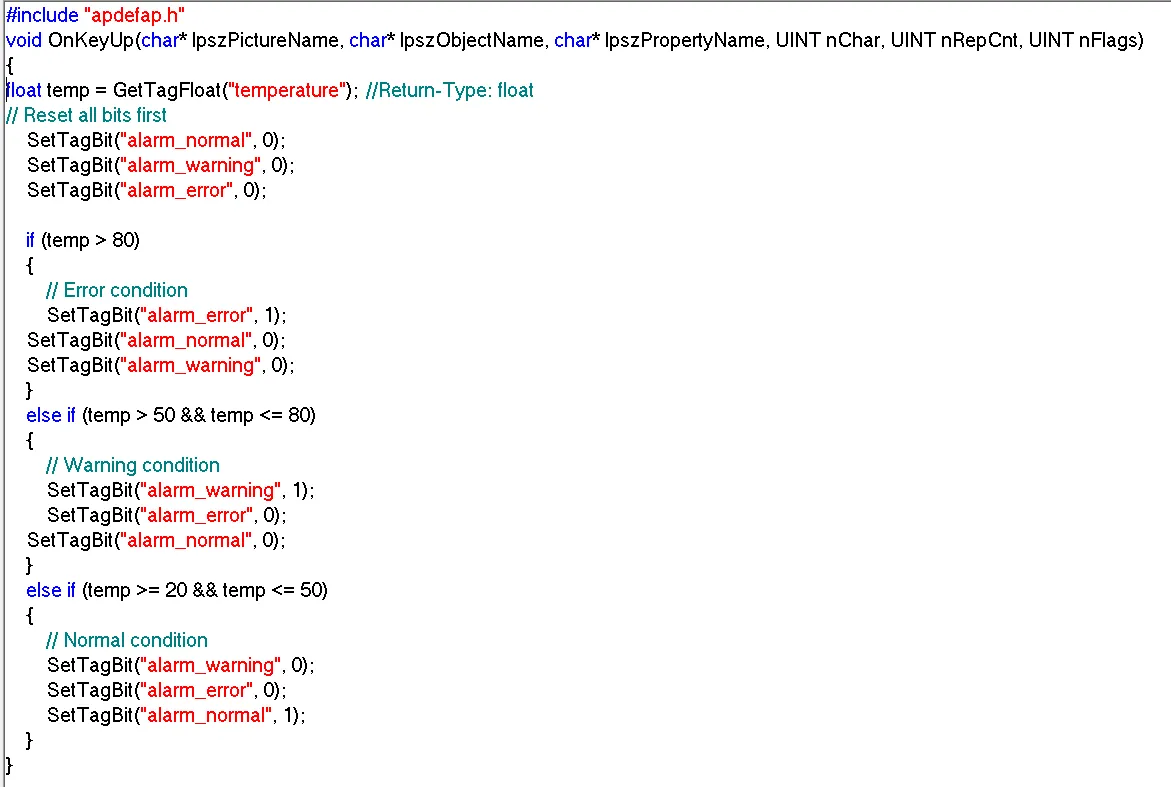
This section explains how to use a C action script in WinCC SCADA to control alarm indication based on the temperature value. The script reads the current temperature from a floating-point tag and sets one of three alarm states—Normal, Warning, or Error—by updating associated Boolean tags. It first resets all alarm bits to avoid overlap, then activates the appropriate bit depending on the temperature range. This logic is essential for dynamically controlling visual indicators (like colored circles or lamps) on the HMI screen.
WinCC SCADA Alarm Setup
In Siemens WinCC SCADA, alarms are configured to notify operators of important process events, including errors, warnings, and normal operating conditions. These alarms can be set up for both discrete (digital) and analog tags, depending on the requirements of your automation process.
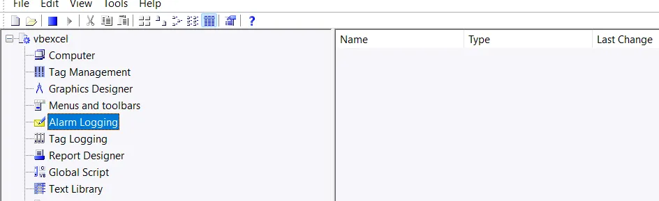
To begin configuring alarms, open the Alarm Logging editor from the WinCC Explorer. This feature allows you to create, organize, and manage alarm messages associated with different process tags. Alarm Logging is an essential tool in WinCC for defining alarm classes, message texts, priorities, acknowledgment requirements, and alarm triggering conditions.
Each alarm can be configured to respond to a specific condition, such as a tag reaching a threshold or a binary input changing state. These alarms are then displayed on the HMI screen through Alarm Views or indicator components, providing real-time feedback to the operator. Proper alarm configuration ensures quicker fault detection, improved system reliability, and reduced downtime in industrial environments.
Alarm Logging Editor Capabilities
Using the Alarm Logging editor in WinCC, you can configure and manage how system alarms and messages are handled. This includes:
- Preparation and configuration of messages
- Real-time display of messages during runtime
- Acknowledgment of alarms and events by the operator
- Archiving of messages for documentation and analysis
- Alarm messages can be triggered by analog or discrete (digital) tags based on defined conditions
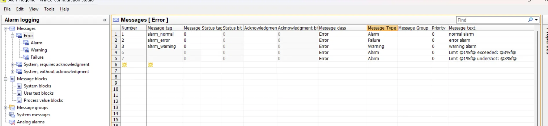
Configure Alarm Logging in WinCC SCADA
In the Alarm Logging editor of WinCC SCADA, you can set up alarms to notify operators of specific process conditions. Start by adding the required tag, then select the type of alarm—analog or discrete. Define a clear message text, which can be selected from predefined options or entered manually as a user-defined message. Assign an appropriate alarm class such as Error, Warning, or Information to categorize the alarm. Repeat this setup for each tag to build a complete and effective alarm system.
Alarm Logging Configuration Covers the Following Topics:
- Configuring the Message System – Set up how alarms are handled and displayed
- Message Blocks – Organize and group related messages
- Message Classes – Define severity levels such as Error, Warning, and Info
- Message Types – Specify analog, digital, operator, or system-triggered messages
- Messages – Create and manage individual alarm messages
- Message Groups – Combine messages for grouped display or handling
- System Messages – Handle predefined system-generated events
- Analog Alarms – Set alarm conditions for analog tag thresholds
- AS Messages – Integrate messages directly from the automation system
- Operator Messages – Log messages triggered by operator actions
WinCC SCADA – Add Alarm Component to Graphics Screen
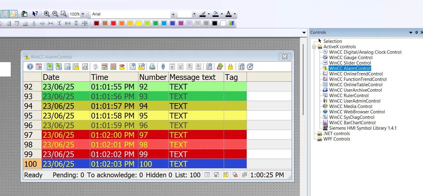
The WinCC AlarmControl is a powerful message display window used in SCADA runtime to show all active, acknowledged, and historical alarm messages. Each alarm is presented in a dedicated message line, with its content defined by configurable message blocks. This allows operators to clearly monitor events and quickly respond to process conditions.
Steps to Configure AlarmControl in Graphics Designer:
- Open the Graphics Designer and go to the Controls tab.
- Select and insert the WinCC AlarmControl into your picture.
WinCC SCADA – Start the Alarm System
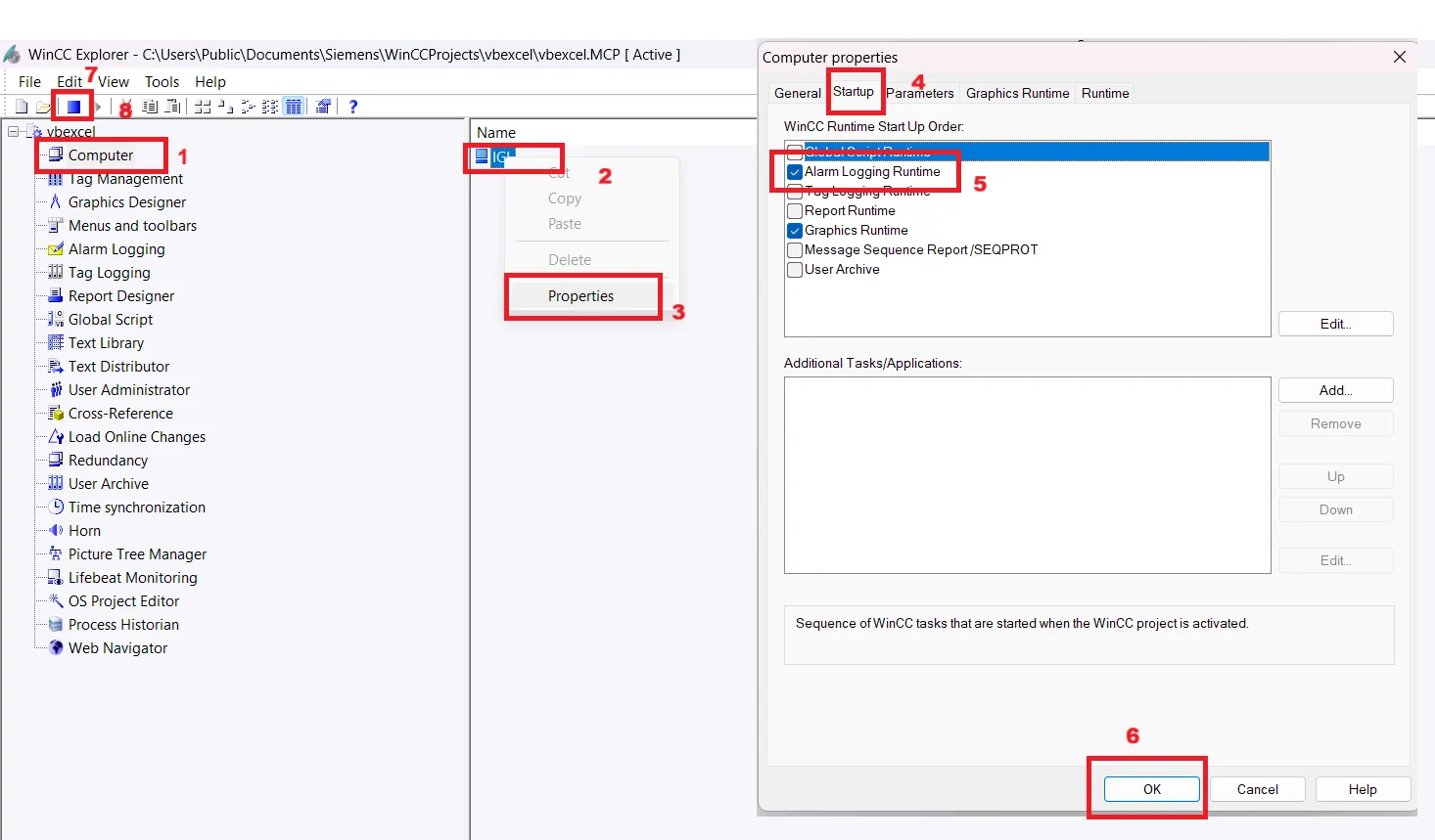
To activate the alarm system in Siemens WinCC SCADA, you must ensure that the Alarm Logging Runtime is enabled during project startup. This setting allows the configured alarm messages to be monitored and displayed during runtime.
Follow these steps to start the alarm system:
- Open WinCC Explorer.
- In the project tree, right-click on the computer name (e.g., Computer_1) under Computer.
- Select Properties from the context menu.
- In the Properties dialog, go to the Startup tab.
- Under the startup options, check the box for "Alarm Logging Runtime".
- Click OK to save the changes.
- Restart the WinCC Runtime or WinCC Server to apply the settings.
Once enabled, the alarm system will start automatically with the runtime environment and begin monitoring the tags and conditions configured in the Alarm Logging editor.
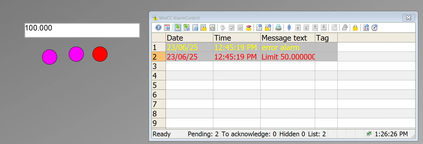
Test and Run Alarm System in WinCC SCADA
Once you have configured tags, messages, and activated the alarm runtime, the next step is to test and observe the alarm system behavior in real-time. You can simulate different process conditions (like temperature changes) to verify how the system reacts and how alarms are displayed. Below are the three types of alarms you should test during runtime:
Normal Alarm
A Normal alarm indicates that the process or system is operating within its expected range and no abnormal conditions are present. This state reassures the operator that all monitored values are stable and under control. In visual representations, the normal state is often shown using a green color.
Warning Alarm
A Warning alarm signals that a process parameter has deviated from its ideal range and may lead to a fault if not addressed. Although the system continues to operate, operator attention is required to prevent escalation. Warning alarms are typically shown in yellow and serve as an early notification to take corrective action.
Error Alarm
An Error alarm indicates a critical failure or serious fault in the system that requires immediate action. It may result in the process stopping or malfunctioning if not resolved. These alarms are designed to alert operators to unsafe or damaging conditions and are usually displayed in red to draw immediate attention.
After testing, ensure each alarm is logged correctly, appears in the AlarmControl window, and can be acknowledged as configured. This final testing phase validates your complete alarm system setup.
Overview of the Message System in WinCC SCADA
The message system in Siemens WinCC SCADA plays a vital role in monitoring and managing both error and operational states of a process. It provides operators and maintenance personnel with real-time insights into system performance and malfunctions, helping to ensure efficient and reliable plant operation.
Key Benefits of the Message System
- Provides access to comprehensive information about error and operating states
- Allows for the early detection of critical situations
- Enables the prevention or reduction of downtimes
- Supports continuous quality improvement
- Allows for targeted documentation of all error and operating conditions