Communication Setup: Siemens WinCC SCADA to Siemens PLC Simulator (PLCSIM)
Share this Page:
Communication Setup: Siemens WinCC SCADA to Siemens PLC Simulator (PLCSIM)
siemens wincc scada is a software which is used for controlling, monitoring, data logging, communication etc. of industrial process control system. PLCSIM is virtual plc simulator used to test s7-300 and s7-400 plc logic without downloading to real controller. Setting up communication between Siemens WinCC scada and the Siemens PLC Simulator (PLCSIM) is essential for testing and developing automation projects without using real hardware. in this article we learn step-by-step guide to help you set up and establish a seamless connection between plc simulator and wincc scada.
1. Create a new project in simatic manager
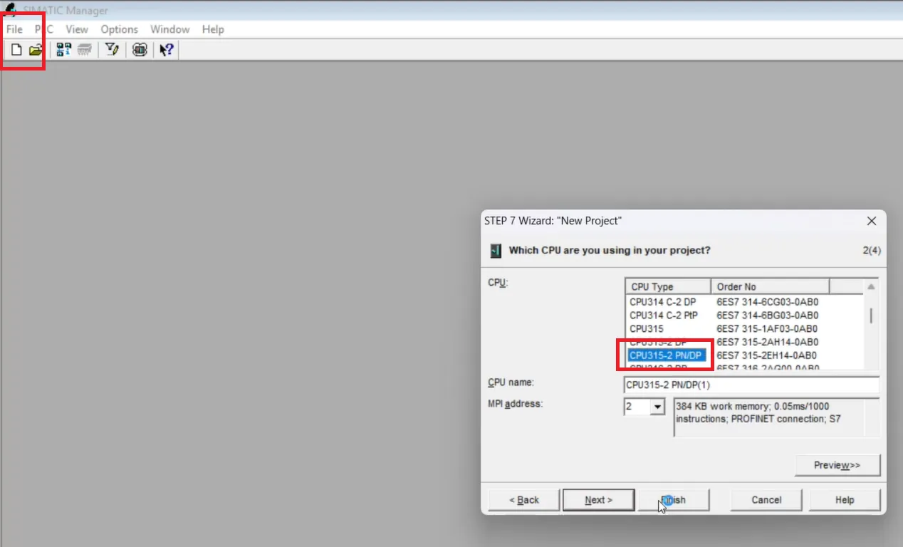
open your simatic manager and create a new project by following these step -
- click to file than select new project wizard.
- click next and select a your plc in this article we select 315-2PN/DP plc and press next.
- select programming language(LAD) and press next.
- enter name of project and click to finish
make a simple ladder logic for your Siemens plc
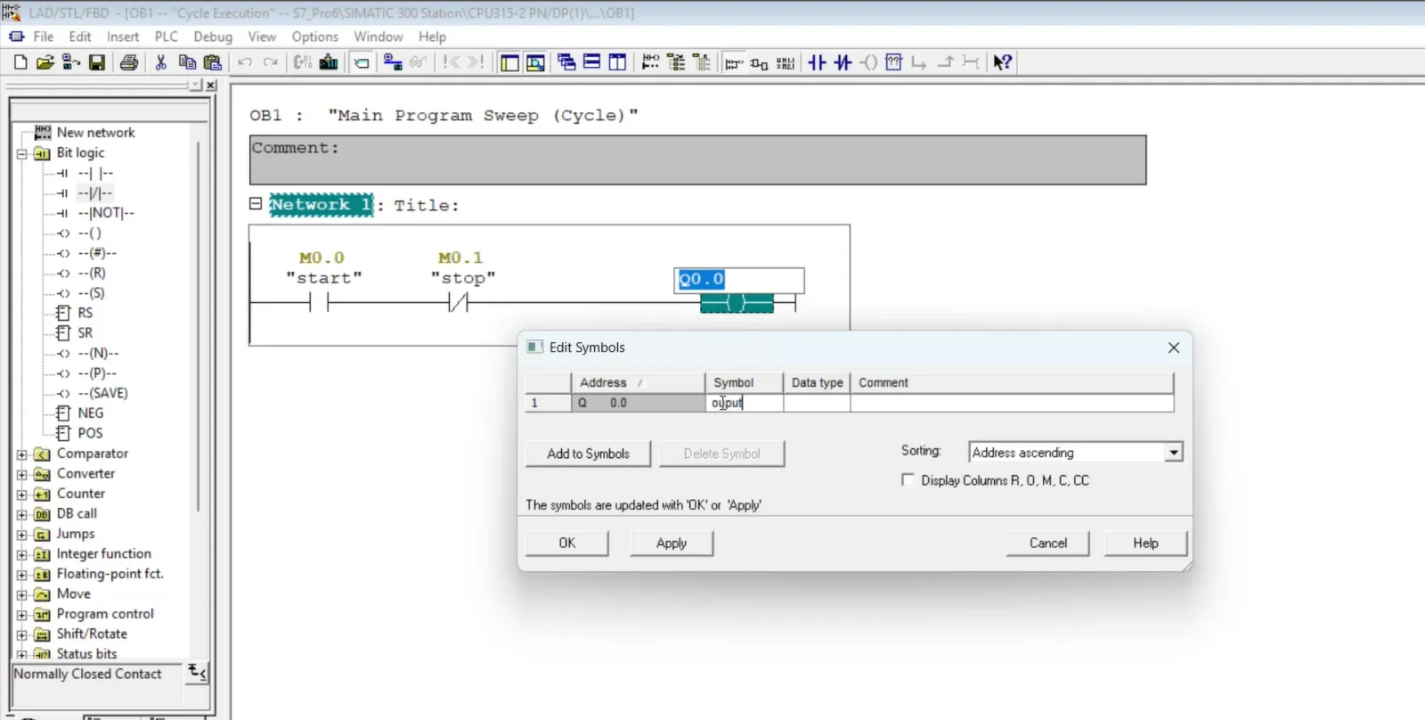
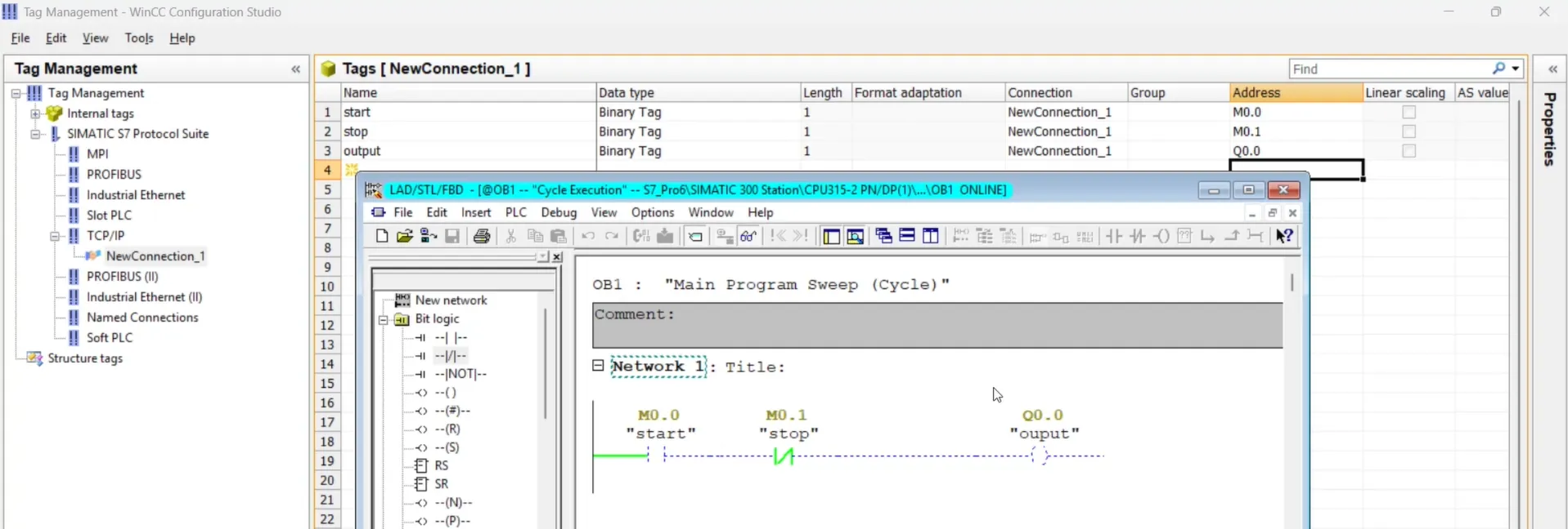
in this article we only use OB1 file for creating project so open OB1 from source and make a simple program. in this program we simply add a NO and NC and coil. as shown in ladder logic. for NO assign M0.0 is a address and symbol is start for NC assign M0.1 as address and define symbol stop. for coil address is Q0.0 and symbol is output it is a example program only for learning purpose.
start plc simulator (PLCSIM) and download project
now save your program(Ctrl+S) and back to simatic manager and click to plc sim icon. your plc simulator will open. now download your complete project to plc simulator and test your program. if your program running correctly move to below steps otherwise fixe issues and than move to next step.
 and download project.webp)
create a new project in wincc explorer
wincc scada is software used to design graphical user interface for industrial control system. Open wincc explorer and create a project by following these steps.
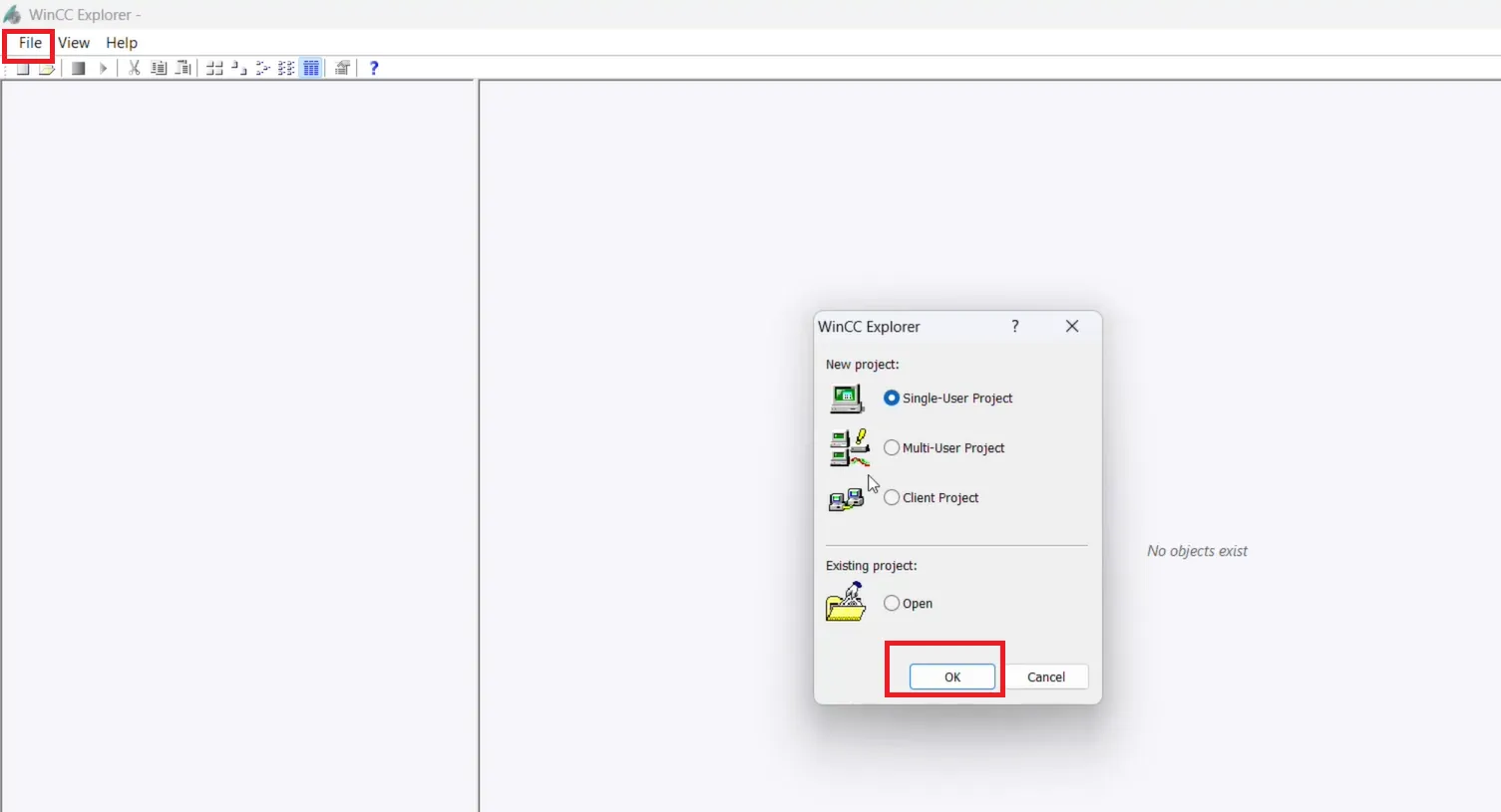
- open wincc explorer as administrator.
- click to file and select new.
- select single user project.
- enter project name and file destination and click to create.
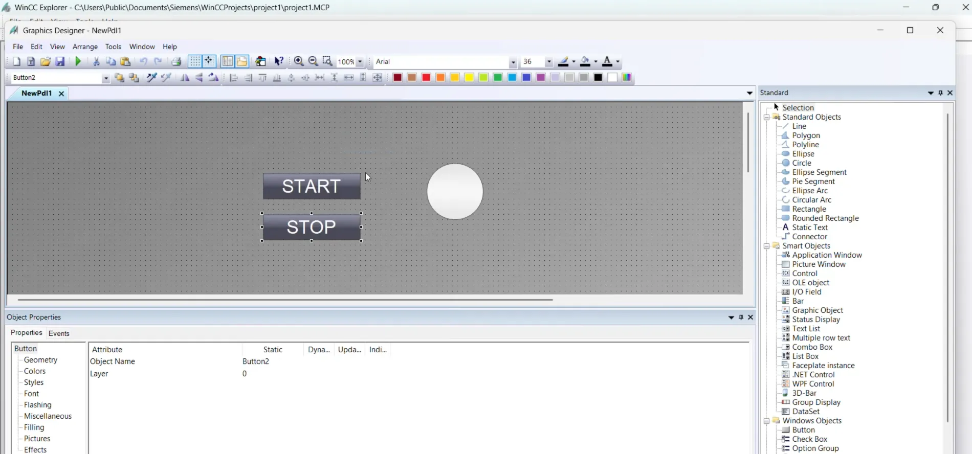
open graphics designer and add component in your screen(picture)
after creating project open graphics designer and add component. for open graphics designer select project and click to graphics designer.
.webp)
now your graphics designer window open in this window add component. in this article we add a start and stop button and a circle. start and stop button set true or false(0 or 1) to your logic and circle background color change when output is set to 1 or 0
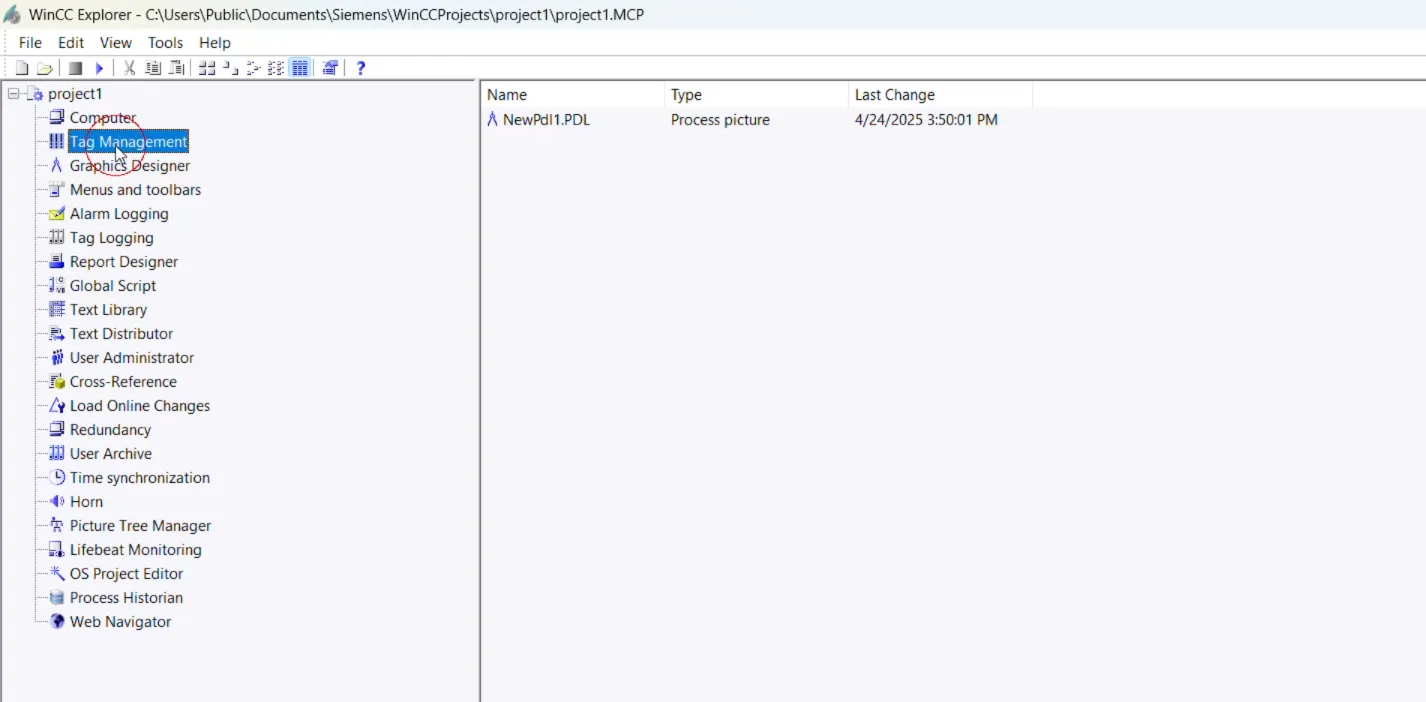
open tag management
Tag Management handles the tags and communication drivers used in the project. Tag Management is an editor in the WinCC Configuration Studio. You open the editor by double-clicking on the "Tag Management" entry in WinCC Explorer.
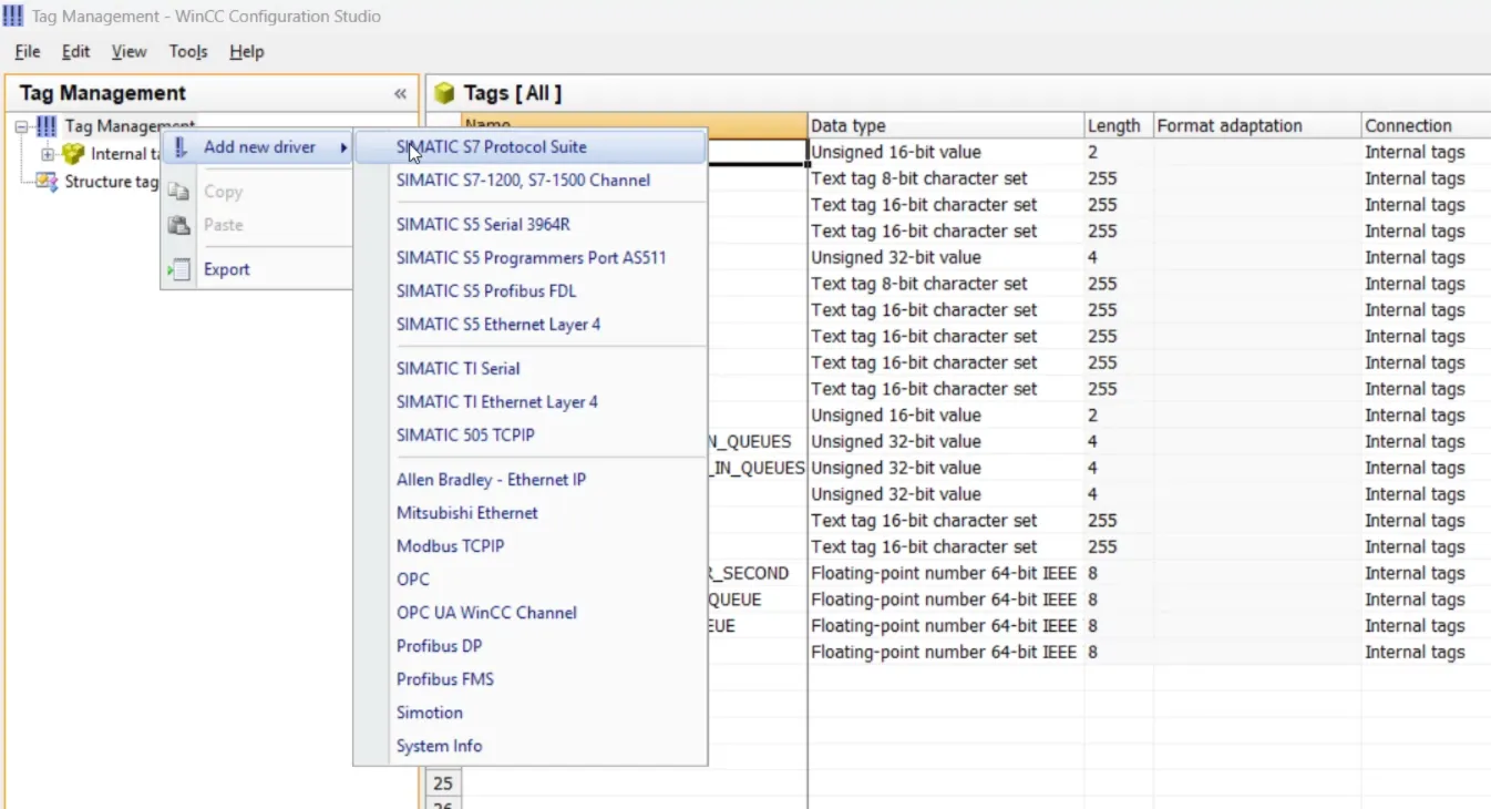
add communication driver in wincc scada tag management
A communication driver is used for communication between WinCC and the connected automation system. right click on tag management - select new driver - select simatic s7 protocol suite.
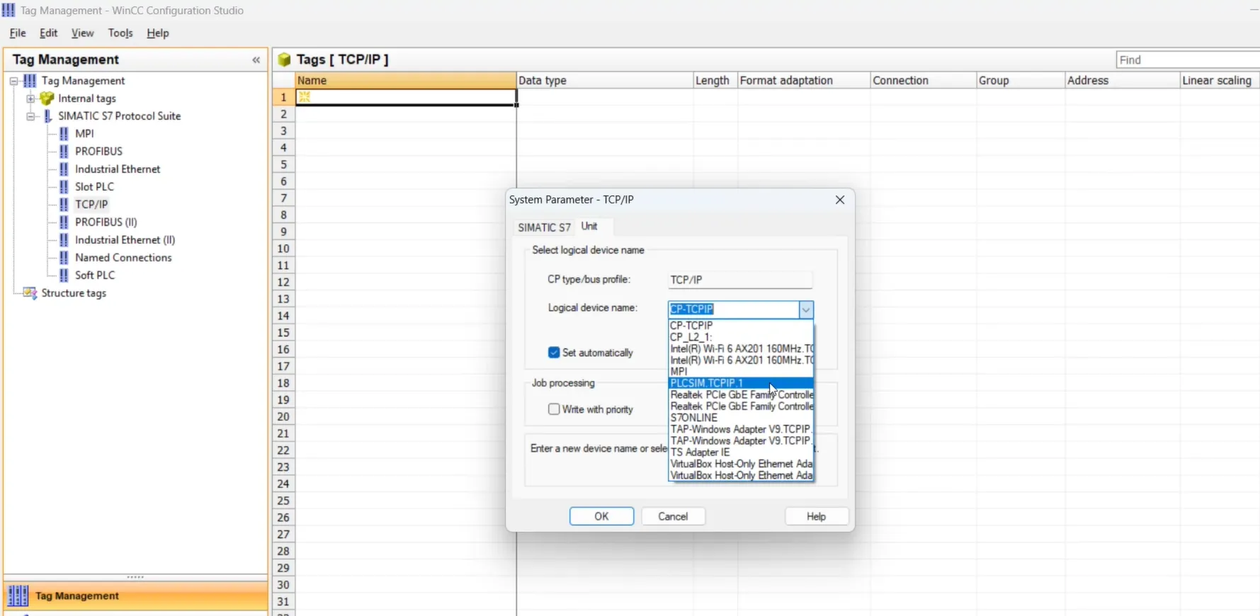
set system parameters for a connection
right click on TCP/IP from simatic s7 protocol suite and select system parameter a dialogue open. in this system parameter dialogue press to unit and from logical device name select plcsim.TCP/IP press ok.
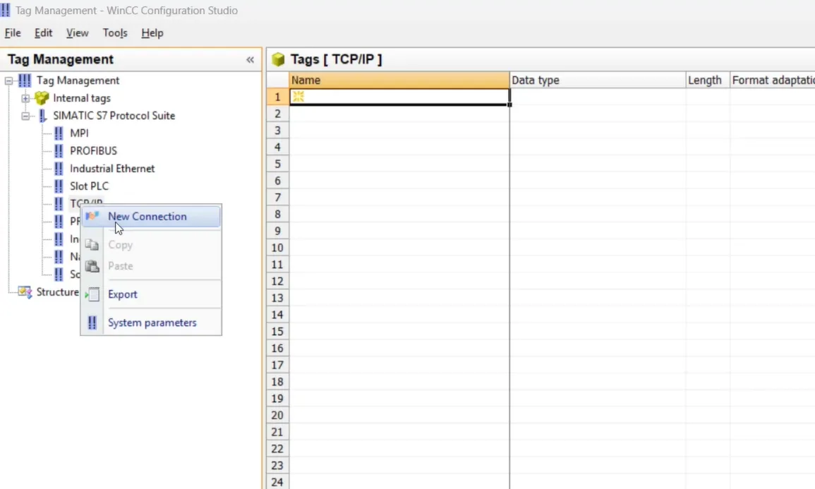
create a new connection for communication
after setting system parameter now right click on TCP/IP and select New connection. if you want to rename enter name otherwise default name is set.
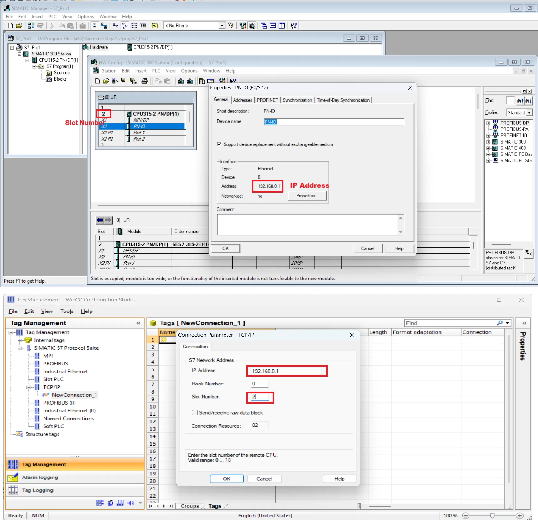
set new connection parameter for plcsim
after adding connection right click on new connection and select connection parameter. a connection parameter dialogue will open here enter carefully all details. in our case we use ip address and slot number of plc for communication. open simatic manager hardware configuration and click to PN/IO copy same op address to connection parameter dialogue and slot number is 2 (default). set to connection parameter and press ok.
add plc tag to tag management in wincc scada
add same tag address in tag management.in our case we set start address M0.0 so same address is assigned in tag management. Add all related tag with same address which you declare in your logic.
define tag in graphics designer button component
open graphics designer and select component. first we assign start tag in start button so select start button and select mouse click event property. in event property click on action and select direct connection. a direct connection dialogue open here select constant put 1 in textbox and select tag form tag option. repeat same for stop button and select stop tag.

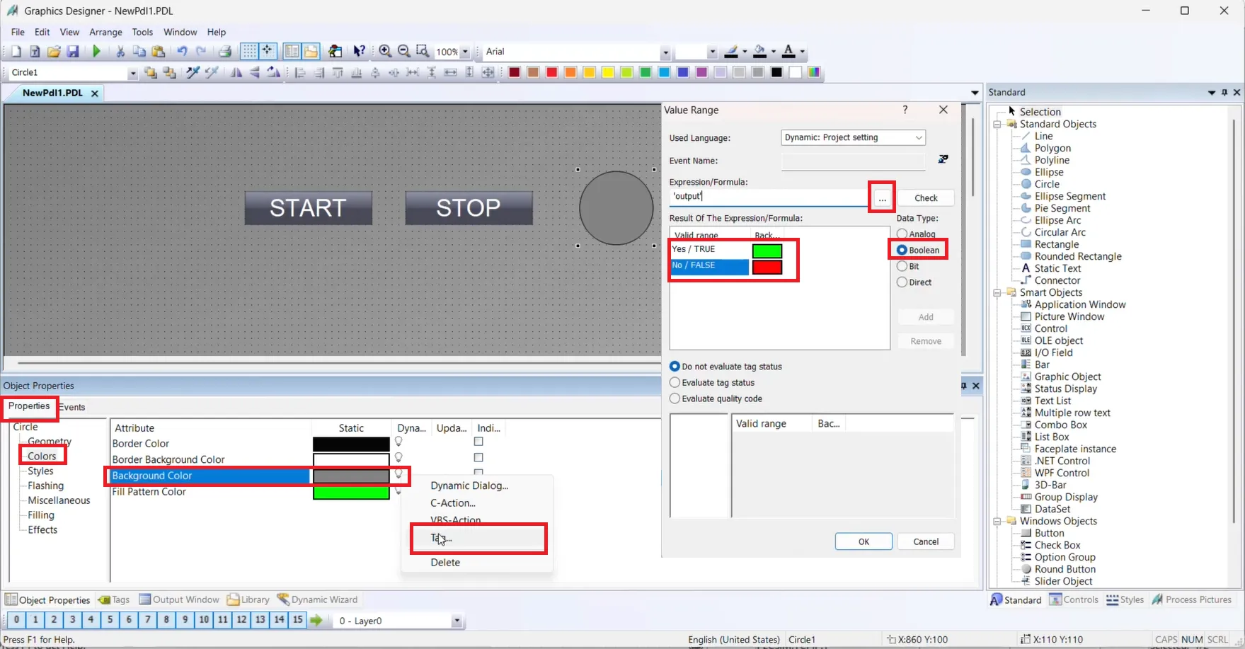
set background color in circle property
select circle and in property select color and click on background color and select tag. a value range dialogue open. here first select data type Boolean. for yes set green color and for no set red color. Select tag output and check error press ok.
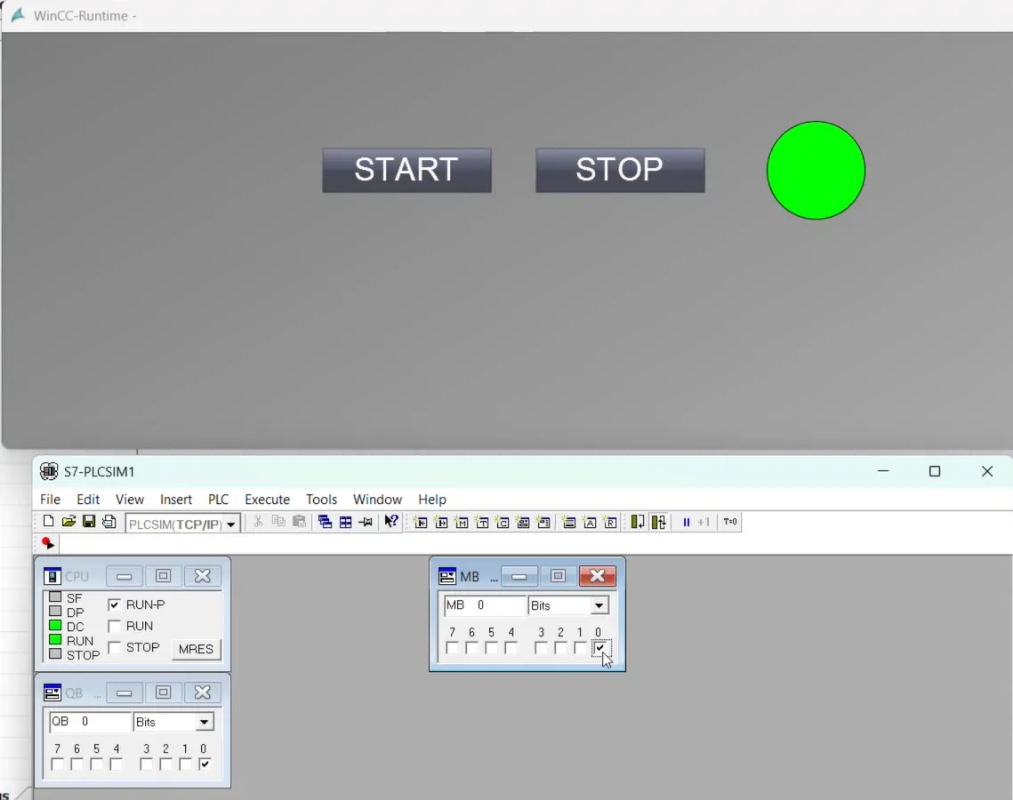
test your graphics in wincc scada runtime
complete all above step and save your project and run winn scada runtime. before running runtime check plc simulator is online and connected with step 7 in RUN mode. once you run wincc runtime plcsim connected with runtime. if start button is pressed it set 1 (true) to start tag(M0.0) if stop button is pressed set M0.1 to 1.color of circle is depend on output Q0.0 if Q0.0 is 1 or true color is green otherwise red.