Siemens PLC Timer Addressing Explained with Simple Examples
Published on Jun06, 2025 | Category: timerShare this Page:
Timers are essential in PLC programming for operations that depend on time-based control. They allow you to execute actions after a specific delay, maintain outputs for a defined period, or control sequences over time. In Siemens PLCs, timers are commonly used in ladder logic programs to manage the timing of various industrial automation tasks, such as motor delays, lamp flashing, or safety interlocks.Each timer has its own unique address that begins with the letter T followed by a number ranging from T0 to T255. These timer numbers are used to reference individual timers within the PLC program.
Siemens timers also use a specific time format to define the duration, known as S5TIME. The time value starts with the keyword S5T# or S5TIME#, followed by the desired time duration (e.g., S5T#10S for 10 seconds, S5T#500MS for 500 milliseconds).
Timers operate only within their specified time intervals and do not continue indefinitely unless programmed to do so. They are an essential tool for implementing precise time-dependent operations in automation projects using TIA Portal and Siemens PLCs.
Types of Timers in Siemens PLC
Siemens PLCs provide several types of timers, including:
- S_PULSE – Pulse S5 Timer: Generates a short pulse for a defined duration once the input condition is true.
- S_PEXT – Extended Pulse S5 Timer: Similar to the pulse timer but allows longer and more precise pulse durations.
- S_ODT – On-Delay S5 Timer: Delays the ON signal after the input condition remains true for the specified time.
- S_ODTS – Retentive On-Delay S5 Timer: Functions like the On-Delay timer but retains its accumulated time value during power loss or input interruption.
- S_OFFDT – Off-Delay S5 Timer: Delays the OFF signal after the input condition goes false, keeping the output on for the specified time.
- SP (---( SP ) – Pulse Timer Coil): Represents a coil in ladder logic that triggers a short pulse.
- SE (---( SE ) – Extended Pulse Timer Coil): Ladder coil for generating extended pulse durations.
- SD (---( SD ) – On-Delay Timer Coil): Ladder logic coil used to implement an On-Delay Timer.
- SS (---( SS ) – Retentive On-Delay Timer Coil): Ladder coil for retentive on-delay timing logic.
- SA (---( SA ) – Off-Delay Timer Coil): Coil that maintains the output after input condition turns false for the specified time.
Siemens PLC Timer Address
Timers have a dedicated memory area reserved in the CPU of a Siemens PLC. Each timer is allocated one 16-bit word in memory. The ladder logic instruction set supports up to 256 timers, with timer addresses ranging from T0 to T255.
Each timer address begins with the letter "T" followed by a number (e.g., T0, T1, T2, ..., T255). The exact range and availability may vary depending on your PLC model, so it's recommended to refer to the official Siemens manual for timer address details.
what is Siemens PLC Timer Value
A timer value represents the duration for which a Siemens PLC timer operates. Each timer is stored as a 16-bit word and runs only for a specific time interval. The timer value is decremented at a fixed interval defined by its time base, and the operation stops when the value reaches zero.
Timer values can be preloaded using two standard formats:
- W#16#wxyz – A hexadecimal format where:
- w = time base (e.g., 0 = 10 ms, 1 = 100 ms, 2 = 1 s, 3 = 10 s)
- xyz = time value in binary coded decimal (BCD)
- S5T#aH_bM_cS_dMS – A user-friendly format where:
- H = hours, M = minutes, S = seconds, and MS = milliseconds
In the S5TIME format, the PLC automatically selects the most appropriate time base and rounds the entered value to the nearest supported unit. This allows easy and readable configuration of time delays in ladder logic.
Examples:
- S5T#8S – 8 seconds
- S5T#1H_05M – 1 hour and 5 minutes
- S5T#2H_02M_18S – 2 hours, 2 minutes, and 18 seconds
what is Timer Base in Siemens PLC
The timer base defines the time interval at which the timer value is decremented by one unit. It determines the resolution of the timer’s countdown and can be set to one of four options depending on the PLC and timer type. The available timer bases are:
- 10 milliseconds (ms) – Smallest time base for high-resolution timing
- 100 milliseconds (ms)
- 1 second (s)
- 10 seconds (s) – Largest time base for long-duration timing
Selecting the correct timer base is essential for accurate timing operations. The PLC often chooses the most suitable timer base automatically based on the preset timer value. Refer to your Siemens PLC manual to understand which timer bases are supported on your specific CPU model.
The maximum timer value that can be set is 9,990 seconds, equivalent to 2 hours, 46 minutes, and 30 seconds.
Siemens PLC Timer Input and Output
Each timer function block in Siemens PLC has specific inputs and outputs, which define its operation. These inputs and outputs have different data types and purposes. Understanding them is essential for effective use of timers in your logic program.
Inputs of a Timer
- T No: Timer identification number; the valid range depends on the CPU model.
- S: A Boolean input used to start or activate the timer operation.
- TV: The preset time value for the timer. It uses the
S5TIMEdata type, for example:S5T#10S. - R: A Boolean input used to reset the timer operation immediately.
Outputs of a Timer
- Q: The main output of the timer. It is Boolean and becomes TRUE or FALSE based on the timer condition.
- BI: The remaining time value, represented in integer format (milliseconds or seconds depending on timer base).
- BCD: The remaining time value in Binary Coded Decimal (BCD) format.
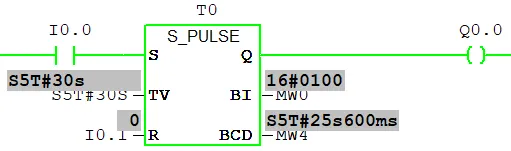
Siemens PLC S-PULSE Pulse Timer
The S_PULSE timer is a simple pulse generator that runs for a specific time interval defined by the timer input TV (Timer Value). For example, if the timer value is set to S5TIME#10S and the timer input (S) is set to high (ON), the timer starts and its output (Q) is set to high. When the preset timer value elapses, the output returns to low. The current timer value is equal to the initial TV minus the time elapsed since the timer started. below is the example of simple siemens plc s_pulse timer.
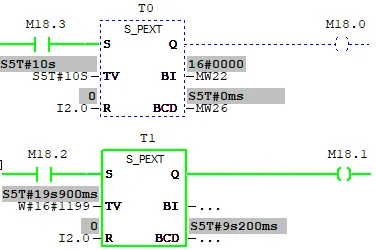
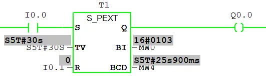
Siemens PLC S_PEXT Extended Pulse Timer
The S_PEXT timer runs for the preset time interval specified at the input TV, even if the signal at the S input turns off before the time interval completes. The output Q remains high ("1") as long as the timer is active. If the signal at input S changes from "0" to "1" while the timer is still running, the timer is restarted (re-triggered) with the preset time value, effectively extending the pulse duration.
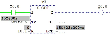
Siemens PLC S_ODT On-Delay Timer
The S_ODT (On-Delay Timer) starts counting when the input signal (S) is set to HIGH. The timer runs for the duration defined by the preset time value (TV), as long as the input S remains HIGH. During the timing operation, the output (Q) remains LOW. Once the preset time has elapsed, the output Q switches to HIGH.
If the reset input (R) changes from LOW to HIGH while the timer is running, the timer is immediately reset, and the output Q returns to LOW.
Important Notes:
- If the input S changes from HIGH to LOW while the timer is still running, the timer pauses but does not reset.
- If the input S is set to HIGH again after being LOW, the timer restarts from the beginning.
- The output Q is set to HIGH only after the preset time interval has fully elapsed.
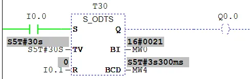
Siemens PLC S_ODTS Retentive On-Delay Timer
The S_ODTS (Retentive On-Delay Timer) begins timing when the input signal (S) is set to HIGH. It counts for the duration specified at the preset time value (TV). Unlike the standard On-Delay timer, the S_ODTS retains the elapsed time even if the input S changes from HIGH to LOW before completion. This means the timer continues counting in the background.
Once the preset time has fully elapsed, the output (Q) is set to HIGH, regardless of the current state of the input signal S. The timer will restart (re-trigger) with the same preset time if the input S transitions from LOW to HIGH again while the timer is already running.
The timer is reset only when the reset input (R) changes from LOW to HIGH, regardless of the state of input S. Once reset, the output Q returns to LOW, and the accumulated time is cleared.
Key Characteristics:
- If the input S goes LOW while the timer is running, the timer retains its progress and continues counting in the background.
- Reapplying HIGH to the input S resumes the timer from where it left off (not from zero).
- The timer must be reset via the reset input R to restart the timing operation from the beginning.
- The output Q turns HIGH only after the preset time has fully elapsed, regardless of input S.
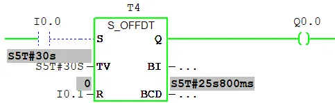
Siemens PLC S_OFFDT Off-Delay Timer
The S_OFFDT (Off-Delay Timer) is triggered by a negative edge at the input signal S — that is, when the signal transitions from HIGH to LOW. Once activated, the output Q remains HIGH as long as the input S is HIGH or while the timer is counting down.
When the signal at input S goes LOW, the timer begins counting down based on the preset time value (TV). During this delay period, the output Q continues to stay HIGH. Once the timer finishes its countdown, the output Q switches to LOW.
The timer is reset immediately if the reset input R changes from LOW to HIGH while the timer is running. Additionally, if input S transitions from LOW back to HIGH during the countdown, the timer is reset, and the output Q remains HIGH. The timer will not restart until S changes from HIGH to LOW again.
Key Characteristics:
- The timer starts only when a negative edge (HIGH to LOW) is detected at input S.
- While the timer is running, the output Q remains HIGH.
- When the preset time elapses, output Q is set to LOW.
- Resetting the timer via input R immediately stops the countdown and sets Q to LOW.
- The timer will not re-trigger unless S again changes from HIGH to LOW.